NEC PD78214 User Manual
Page 209
180
µ
PD78214 Sub-Series
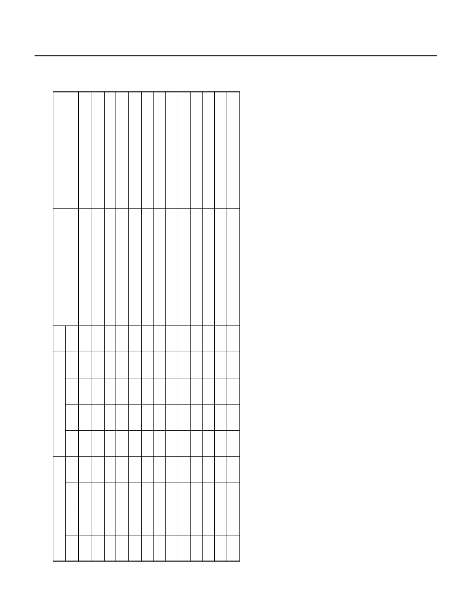
Table 7-15 Timer Output (TO2, TO3) Operation
TOC
0
0
1
1
0
1
1
0
1
1
0
1
1
ENTO3
0/1
0/1
0/1
0/1
0/1
0/1
0/1
0/1
0/1
0/1
0/1
0/1
0/1
AL
V3
0
1
0
1
1
0
1
1
0
1
1
0
1
ENTO2
0/1
0/1
0/1
0/1
0/1
0/1
0/1
0/1
0/1
0/1
0/1
0/1
0/1
AL
V2
×
0
0
0
0
0
0
1
1
1
1
1
1
MOD1
×
0
0
0
1
1
1
0
0
0
1
1
1
MOD0
Ч
Ч
Note
×
Note
×
Note
0
0
0
0
0
0
0
0
0
CLR22
Ч
Ч
Ч
Ч
0
0
0
0
0
0
1
1
1
CLR21
Ч
Ч
Ч
Ч
0
0
0
0
0
0
0
0
0
CMD2
CRC0
TO3
TO2
T
ied high/low
T
ied high/low
T
oggle output (low/high active)
T
oggle output (low/high active)
T
ied high/low
T
oggle output (low/high active)
T
oggle output (low/high active)
T
ied high/low
PWM output (high/low active)
PWM output (high/low active)
T
ied high/low
T
oggle output (low/high active)
T
oggle output (low/high active)
T
ied high/low
T
oggle output (low/high active)
T
ied high/low
T
oggle output (low/high active)
PWM output (high/low active)
T
ied high/low
PWM output (high/low active)
PWM output (high/low active)
T
ied high/low
PWM output (high/low active)
PPG output (high/low active)
T
ied high/low
PPG output (high/low active)
TMC1
Note
Usually
, CLR22 = 0 for these cases.
Remarks
1.
The numbers 0 and 1 of "0/1" in the AL
V3 and AL
V2 columns correspond to the words high and low of "high/low" in the TO3
and TO2 columns, respectively.
2.
The character
×
represents the value 0 or 1.
3.
No combinations other than those indicated in this table are allowed.