NEC PD78214 User Manual
Page 206
177
Chapter 7 Timer/Counter Units
7
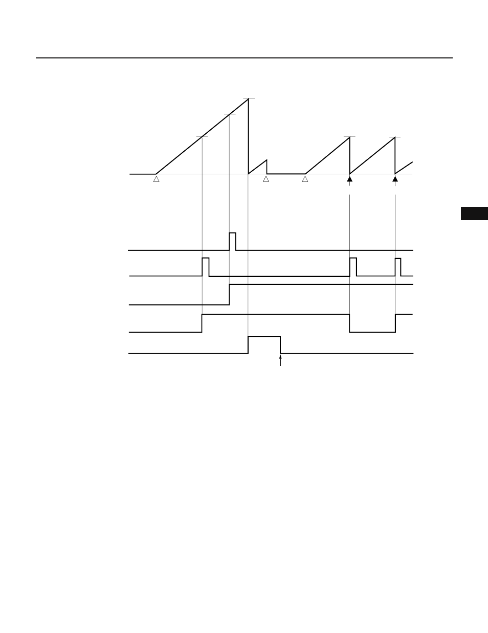
Fig. 7-81 TM2 Cleared After a Coincidence Is Detected
Remark CLR22 = 0
Caution When using an in-circuit emulator, see the notes described in Section 7.5.4.
(2) Capture operation
Eight-bit timer/counter 2 performs a capture operation to load the count value of the timer into the capture
register in synchronism with an external trigger.
As an external trigger, a valid edge detected on the external interrupt request (INTP1) input pin is used (capture
trigger). In synchronism with a capture trigger, the count value of 8-bit timer 2 (TM2) in count operation is
loaded and held in the CR22 capture register. After the value captured in the CR22 register is read by the
program, the value of the CR22 register becomes undefined.
A valid edge used as a capture trigger is set using external interrupt mode register 0 (INTM0). When both a
rising edge and falling edge are set as capture triggers, the pulse width of an applied external signal can be
measured. When a capture trigger is generated using one edge, the period of an input pulse signal can be
measured.
For the detailed format of the INTM0 register, see Fig. 11-1 in Chapter 11.
Cautions
1. The value of the CR22 register, after being read, becomes undefined. A captured value can be used more than once by
saving the captured value to a register or memory.
2. When using an in-circuit emulator, see the notes described in Section 7.5.4.
INTC20
INTC21
TO2 pin output
ENTO2
←1
ALV2
←1
Count starts
CE2
←1
CLR21
←0
FFH
CE2
←0
CE2
←1
CLR21
←1
CR20
CR21
CR21
CR21
Cleared
Cleared
Count starts
Count stops
0H
TM2
count value
TO3 pin output
ENTO3
←1
ALV3
←1
OVF2
Inactive level
Cleared by software
Inactive level
(
(
(
(
(
(
(
(