Chapter 10 clock synchronous serial interface – NEC PD78214 User Manual
Page 310
281
Chapter 10 Clock Synchronous Serial Interface
10
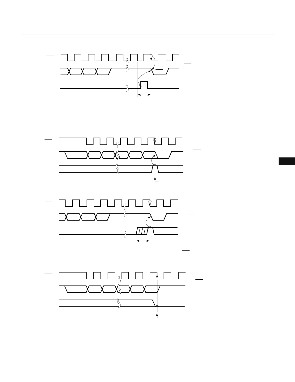
Fig. 10-23 ACKT Operation
Caution Do not set ACKT before transfer has been completed.
Fig. 10-24 ACKE Operations
(a) When ACKE is set to 1 at the end of transfer
(b) When ACKE is set after transfer has been completed
(c) When ACKE is set to 0 at the end of transfer
SCK
6
7
8
9
D2 D1 D0
SB0
ACK
ACKT
ACK signal is output during first clock
cycle immediately after ACKT is set.
When set during this period
SCK
1
2
7
8
D7 D6 D2 D1
SB0
D0
9
ACK
ACKE
When ACKE = 1 at this point
The ACK signal is output
during the ninth clock
cycle
SCK
6
7
8
9
D2 D1
D0
SB0
ACK
ACKE
The ACK signal is output
during the first clock cycle
immediately after ACKT is set.
When ACKE is set during this period and ACKE = 1 at
the falling edge of the next SCK
SCK
1
2
7
8
D7
D6
D2
D1
SB0
D0
9
ACKE
The ACK signal is not
output
When ACKE = 0 at this point