Chapter 10 clock synchronous serial interface – NEC PD78214 User Manual
Page 314
285
Chapter 10 Clock Synchronous Serial Interface
10
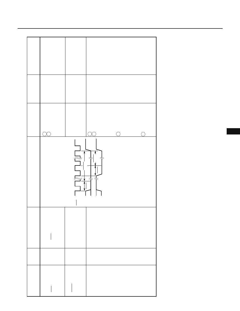
Table 10-2 Signals in SBI Mode (2/3)
Low signal output to SB0
within a single cycle of
the SCK clock after serial
reception has been
completed
Low sgnal output to
SB0, following the
acknowledge signal
High signal output to
SB0 before serial
transfer is started and
after serial transfer is
completed
Acknowledge
signal
(ACK)
Busy signal
(BUSY)
Ready signal
(READY)
Output
device
Definition
1
ACKE is set to 1.
2
ACKT is set.
•
BSYE is set to 1.
1
BSYE is set to 0.
2
When CTXE is set
to 1, data is
written into the
SIO (a serial
transfer start is
specified).
Note 2
3
When CTXE is set
to 0 and CRXE is
set to 1, the
instruction to read
data from the SIO
is executed.
4
The CRXE bit is
changed from 0
to 1.
Output condition
•
ACKD is set.
Influence on flag
Description
Reception is completed.
Because an operation is
currently in progress,
serial transmission or
reception is disabled.
Serial transmission or
reception is permitted.
Signal name
T
iming chart
READY
READY
ACK
SCK
D0
D0
SB0
SB0
9
BUSY
ACK
BUSY
—
—
Master/
slave
Slave
Slave