Chapter 7 timer/counter units – NEC PD78214 User Manual
Page 170
141
Chapter 7 Timer/Counter Units
7
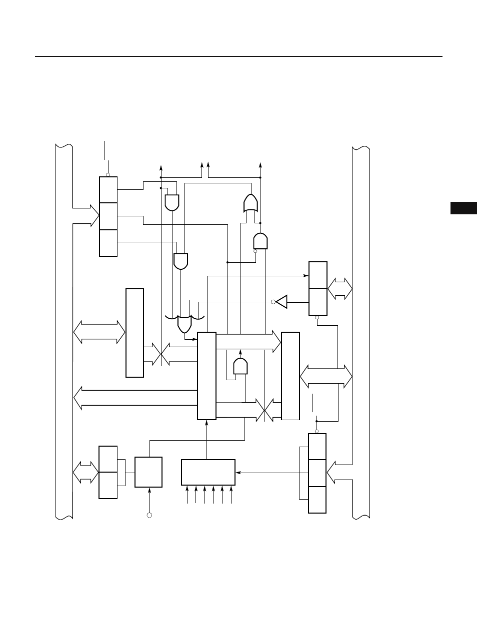
Fig. 7-43 Block Diagram of 8-Bit Timer/Counter 1
Internal bus
8
8
PRS12
ES01
Timer control
register 0
(TMC1)
Clear
PRS11
PRS10
RESET
8
8
8
8
8
8
8
CE1
OVF1
8
Internal bus
Overflow
RESET
8
(CRC1)
CLR11
CM
CLR10
RESET
INTC10
INTC11
Real-time output port
Capture/compare
control register
Compare register (CR10)
8-bit timer 1 (TM1)
Capture/compare
register (CR11)
Caapture trigger
ES00
(INTM0)
INTP0
MPX
External interrupt
mode register 0
Edge
detector
1/8
f
CLK
/512
Prescaler mode
register (PRM1)
f
CLK
/256
f
CLK
/128
f
CLK
/64
f
CLK
/32
f
CLK
/16