Chapter 7 timer/counter units – NEC PD78214 User Manual
Page 150
121
Chapter 7 Timer/Counter Units
7
(1) Basic operation
By setting ENTOn (n = 0, 1) of the timer output control register (TOC) to 1, the timer outputs (TO1, TO0) can
be changed with the timing determined by MOD0, MOD1, and CLR01 of capture/compare control register 0
(CRC0).
In addition, by clearing ENTOn (n = 0, 1) to 0, the levels of the timer outputs (TO1, TO0) can be tied. The level
where an output is tied is determined by ALVn (n = 0, 1) of the timer output control register (TOC). When ALVn
(n = 0, 1) is 0, the output is tied high; when ALVn (n = 0, 1) is 1, the output is tied low.
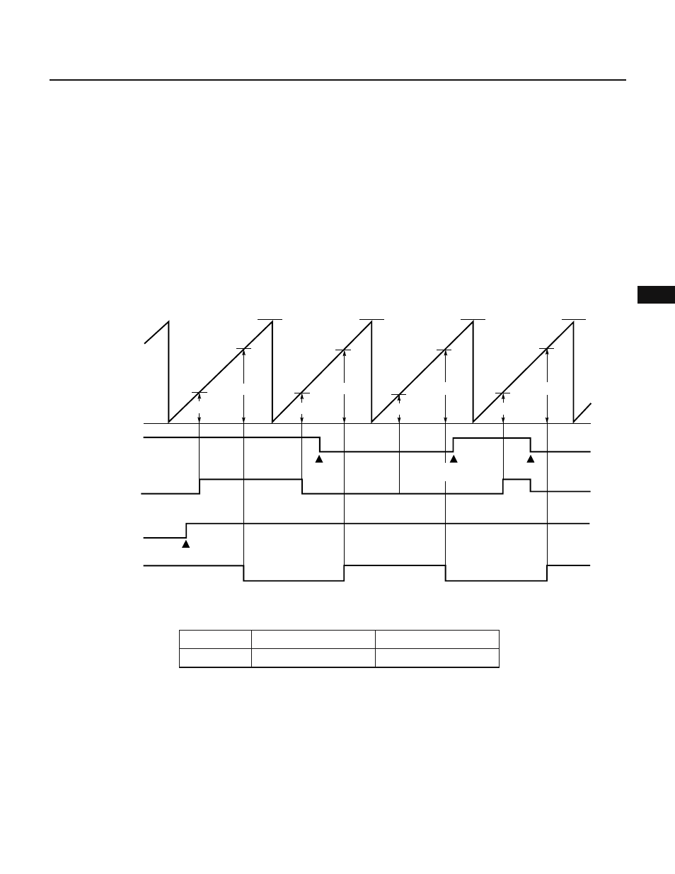
(2) Toggle output
Toggle output is an operation mode where the level of output is inverted each time the value of a compare
register (CR00, CR01) coincides with the value of 16-bit timer 0 (TM0). The output level of TO0 is inverted when
the value of CR00 coincides with the value of TM0. The output level of TO1 is inverted when the value of CR01
coincides with the value of TM0.
Fig. 7-12 Toggle Output Operation
Table 7-6 TO0 and TO1 Toggle Output (f
CLK
= 6 MHz)
Count clock
f
CLK
/8
Minimum pulse width
1.3
µs
Maximum interval
87.4 ms
FFFFH
FFFFH
FFFFH
FFFFH
TM0
count value
0H
ENTO0
Value of CR00
Value of CR01
Instruction
execution
Instruction execution
ENTO1
Output of TO0
(ALV0 = 1)
Output of TO1
(ALV1 = 0)
Value of CR01
Value of CR00
Instruction
execution
Instruction
execution
Value of CR00
Value of CR01
Value of CR00
Value of CR01