NEC PD78214 User Manual
Page 49
20
µ
PD78214 Sub-Series
Product
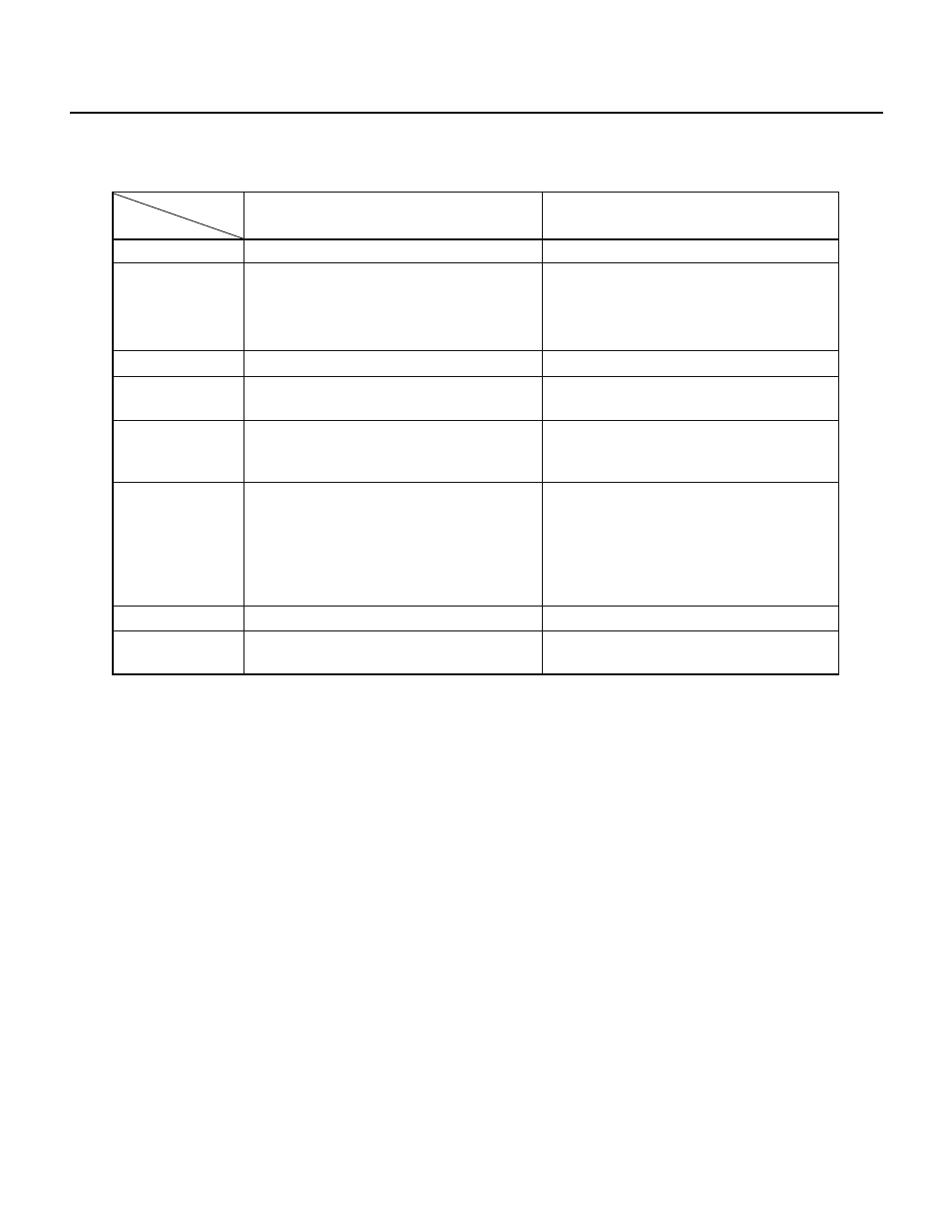
Item
RAM capacity
I/O pins
Timer/counter
Serial interface
Interrupt
A/D converter
Package
Others
µPD78213
512 bytes
• Software programmable pull-up resistors:
Supported
• Transistor direct drive outputs: Supported
PWM/PPG output: Supported
Scaler for the baud rate generator output:
Supported
Macro service can be applied to all interrupt
requests with the exception of that caused by
a serial receive error.
• Eight input pins.
• A voltage ranging from 0 V to AV
REF
can be
applied only to those pins for which A/D
conversion is being performed, as well as
the pins selected by the ANI0 to ANI3 bits
of the ADM register.
64-pin QFP: Supported
The area at addresses 0FE20H to 0FE7FH can
be accessed in any addressing mode.
128 bytes
• Software programmable pull-up resistors:
Not supported
• Transistor direct drive outputs: Not
supported
PWM/PPG output: Not supported
Scaler for the baud rate generator output:
Not supported
Macro service can be applied to some
interrupt requests.
• Six input pins.
• A voltage ranging from 0 V to AV
REF
can be
applied to the input pins.
64-pin QFP: Not supported
The area at addresses 0FE20H to 0FE7FH can
only be accessed in saddr addressing mode.
µPD78210
1.7 DIFFERENCES BETWEEN THE
µPD78210
Note
AND
µPD78213
Note For maintenance purposes only.