4 built-in pull-up resistor, Chapter 5 port functions – NEC PD78214 User Manual
Page 120
91
Chapter 5 Port Functions
5
(3) Control pins
When port 6 function as control pins, they cannot be manipulated or tested by software.
(4) Analog inputs (P66 and P67 only)
When port 6 is used as analog input pins (AN6 and AN7), the level of each pin can be read and tested.
5.7.4 Built-In Pull-Up Resistor
P64 through P67 have built-in pull-up resistors. When they must be pulled up, the built-in pull-up resistors should
be used. Use of the built-in pull-up resistors can reduce the number of the required components and the required
installation space.
Use of a built-in pull-up resistor can be specified for each of these pins, independently of the other pins, by the
PUO6 bit of pull-up-resistor-option register (PUO) and the port 6 mode register (PM6).
When the PUO6 bit is 1, the built-in pull-up resistor for a pin specified by the PM6 (PM6n = 1, n = 4 to 7) is connected.
P60 through P63 do not have a built-in pull-up resistor.
Fig. 5-41 Pull-Up-Resistor-Option Register Format
Remark Resetting the PUO to 00H can reduce the required current in the STOP mode.
Caution To use P66 and P67 as AN6 and AN7, respectively, it is necessary to reset the PU06 bit to 0; do not specify to use built-in pull-up
resistors for port 6.
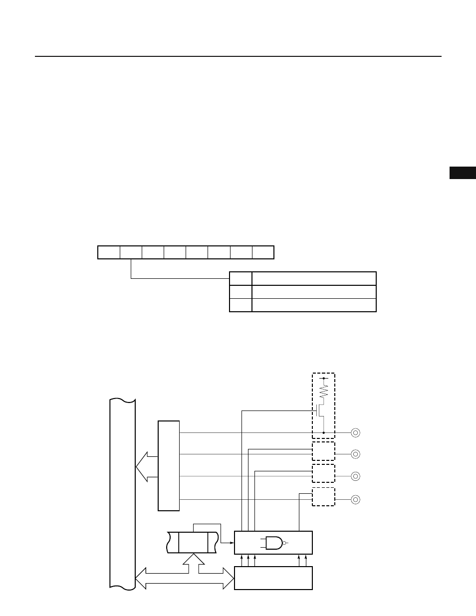
Fig. 5-42 Connection of Pull-Up Resistors (Port 6)
0
7
PUO6
6
PUO5
5
PUO4
4
PUO3
3
PUO2
2
0
1
0
0
PUO
PUO6
Connected with port 6
Not connected with port 6
Specifies pull-up resistor connection of port 6
(00H when RESET is input)
0
1
Internal bus
V
DD
P64
P65
P66
P67
Input buffer
PUO6
(PUO)
• • •
Port 6 mode
register (PM6)