NEC PD78214 User Manual
Page 201
172
µ
PD78214 Sub-Series
The count operation of TM2 is controlled by the CE2 bit of the TMC1 register as in the case of basic operation.
When the CE2 bit is set to 1 by software, TM2 is cleared to 00H by the first count clock pulse, then count-up
operation starts.
When the CE2 bit is set to 0 by software during TM2 count operation, TM2 is cleared to 00H by the next count
clock pulse, and count operation stops. If the CE2 bit is set to 1 by software when the CE2 bit is already set
to 1, TM2 count operation is not affected.
Cautions
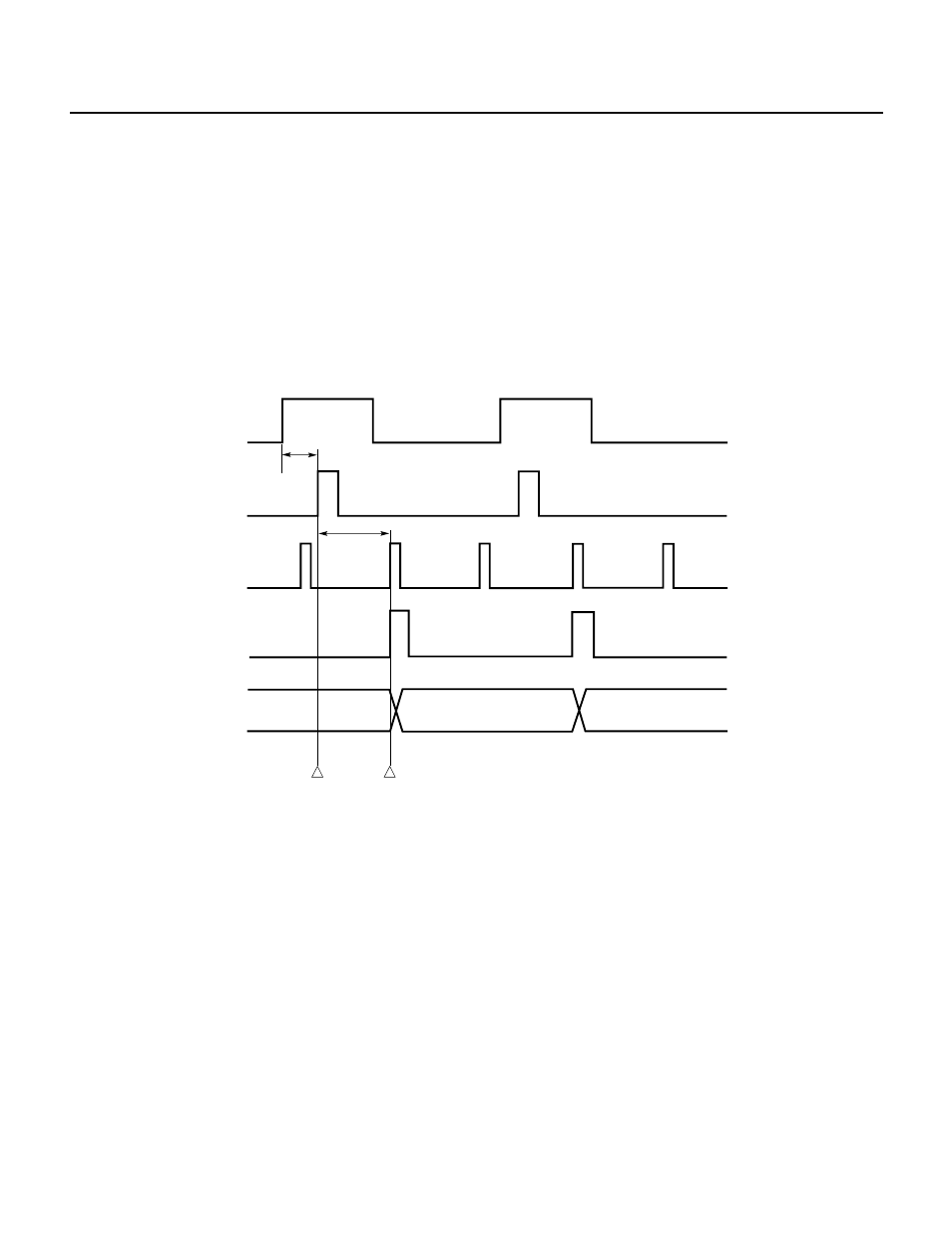
1. When 8-bit timer/counter 2 is used as an external event counter, the increment of TM2 lags the input of a valid edge to
the CI pin by a maximum of 28 system clock pulses (4.67
µs: f
CLK
= 6MHz). This means that TM2 may not be incremented
yet when read immediately after an edge is detected. In addition, the generation of an interrupt request by a coincidence
with a compare register (CR20, CR21) lags the input of an edge. Take this point into consideration when short-period
timing control is required after input of an edge.
Fig. 7-76 Interrupt Request Generation Using External Event Counter
Countable
timing of
TM2
TM2
n
n-1
n+1
ICI
CI
8 to 12 clocks
16 clocks (Max.)
Count clock of
TM2
INTP2 occurs
here
TM2 counts up here
or is compared with
compare register.
ICI: Signal that has gone
through the edge
detector of CI input
2. When 8-bit timer/counter 2 is used as an external event counter, TM2 alone cannot distinguish between the state where
no valid edge is applied and the state where only one valid edge has been applied. (See Fig. 7-77.) In either case, the value
of TM2 is 0. When the states need to be distinguished from each other, use the INTP2 interrupt request flag. (The same
pin is used as the INTP2 pin as well as the CI pin, so that the functions can be used at the same time.) Fig. 7-78 shows
an example of distiction.