6 sbi communication and signals, 1 bus release signal (rel), Chapter 10 clock synchronous serial interface – NEC PD78214 User Manual
Page 306
277
Chapter 10 Clock Synchronous Serial Interface
10
10.6 SBI COMMUNICATION AND SIGNALS
This section describes the format of the SBI serial data and signals to be used.
Serial data transferred via SBI can be divided into three groups: address, command, and data. Each frame of serial
data is formed as shown below:
(bus release signal) + (command signal) + 8-bit data + ACK + (BUSY)
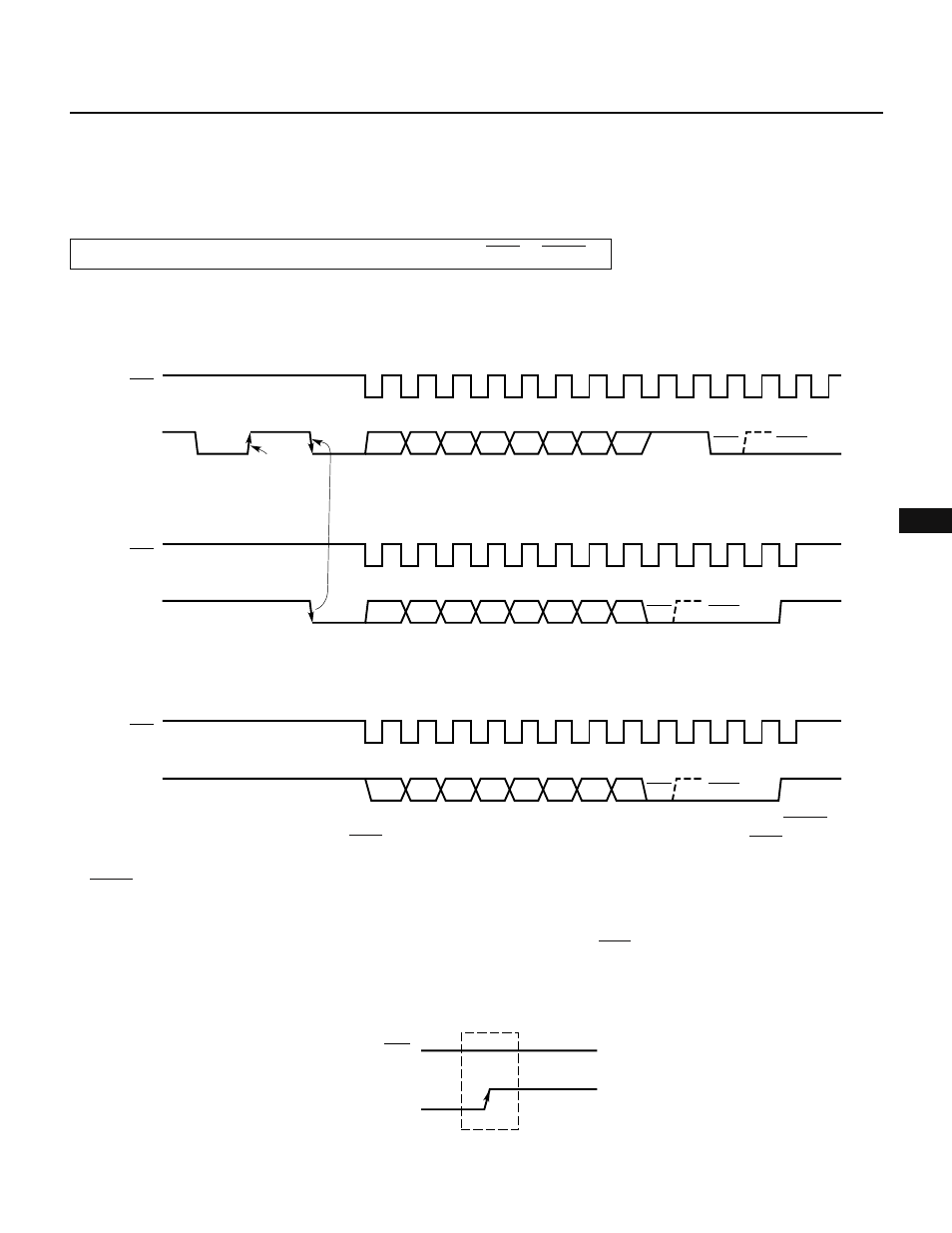
Fig. 10-13 shows the transfer timing of the address, command, and data.
Fig. 10-13 SBI Transfer Timing
SCK
A7
SB0
BUSY
8
9
A0
ACK
SCK
C7
SB0
READY
9
C0 ACK
BUSY
SCK
SB0
8
9
D7
READY
D0 ACK
BUSY
Address transfer
Bus release signal
Command transfer
Command signal
Data transfer
The master device outputs the bus release signal and command signal. The slave device outputs BUSY. Either
the master or slave device can output ACK. (Usually, the device receiving 8-bit data outputs ACK.)
The master device continues serial clock output during the period from the start of 8-bit data transfer to the release
of BUSY.
10.6.1 Bus Release Signal (REL)
The bus release signal is the SB0 line going from low to high while the SCK line is high (the serial clock is not
output). The master device outputs this signal.
Fig. 10-14 Bus Release Signal
SCK
SB0
"H"
The bus release signal indicates that the master device is going to send an address to a slave device. The slave
device contains hardware to detect the bus release signal.