NEC PD78214 User Manual
Page 43
14
µ
PD78214 Sub-Series
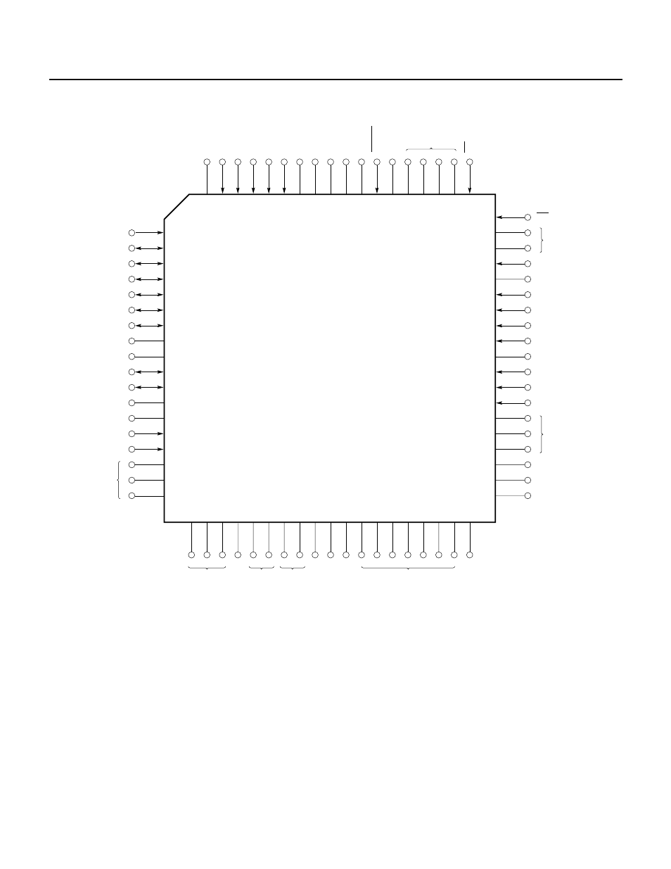
(4) 74-pin plastic QFP (20
× 20 mm)
Caution The symbols enclosed in parentheses indicate that the corresponding pins, not used in PROM programming mode, shall be handled
as follows:
L
: Connect the corresponding pin independently to V
SS
, through a 10-k
Ω resistor.
G
: Connect the corresponding pin to V
SS
.
Open : Leave the corresponding pin unconnected.
Remark The NC pins are not connected inside the chip.
★
CE
A7
(Open)
A6
A5
A4
A3
NC
A2
A1
A0
NC
(Open)
(L)
56
55
54
53
52
51
50
49
48
47
46
45
44
43
42
41
40
39
38
1
2
3
4
5
6
7
8
9
10
11
12
13
14
15
16
17
18
A8
D7
D6
D5
D4
D3
D2
V
SS
IC
D1
D0
(Open)
NC
P20/NMI
A9
(L)
A10
A11
A12
A13
A14
(G)
V
SS
V
SS
(G)
(Open)
RESET
NC
OE
NC
V
PP
V
DD
V
DD
NC
19 20 21 22 23 24 25 26 27 28 29 30 31 32 33 34 35 36 37
PD78P214GJ-5BJ
PD78P214GJ-
×××
-5BJ
µ
µ
(G)
(G)
(Open)
(L)
(L)
(Open)
(L)
(L)
74 73 72 71 70 69 68 67 66 65 64 63 62 61 60 59 58 57