NEC PD78214 User Manual
Page 229
200
µ
PD78214 Sub-Series
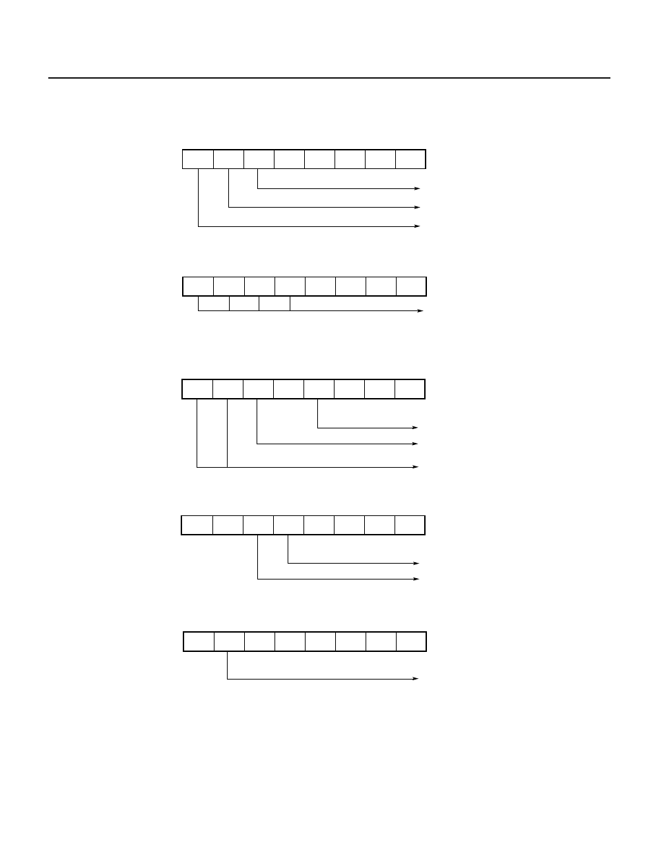
Fig. 7-112 Setting of Control Registers for PPG Output Operation
(a) Timer control register 1 (TMC1)
(b) Prescaler mode register 1 (PRM1)
(c) Capture/compare control register 2 (CRC2)
7
6
5
4
3
2
1
0
1
CRC2
0
1
1
1
0
0
0
Clears when TM2 coincides with CR21
Disables clearing when TM2 is captured
by CR22 register
TO2 is used for PPG output
(d) Timer output control register (TOC)
(e) Port 3 mode control register (PMC3)
7
6
5
4
3
2
1
0
PRS23
×
PRM1
Specifies count clock
(x/f
CLK
; where x = 16, 32, 64, 128, 256 or 512)
PRS22 PRS21 PRS20
Ч
Ч
Ч
7
6
5
4
3
2
1
0
1
0
0
0
Ч
0
0
TMC1
×
Normal mode
Overflow flag
Enables counting for TM2
7
6
5
4
3
2
1
0
1
TOC
0
Ч
Ч
Ч
Ч
TO2 for high-active PWM signal output
Enables PPG output for TO2
Ч
Ч
7
6
5
4
3
2
1
0
1
PMC3
Ч
Ч
Ч
Ч
Ч
Ч
Ч
Specifies P36 pin as TO2 output