Chapter 10 clock synchronous serial interface – NEC PD78214 User Manual
Page 302
273
Chapter 10 Clock Synchronous Serial Interface
10
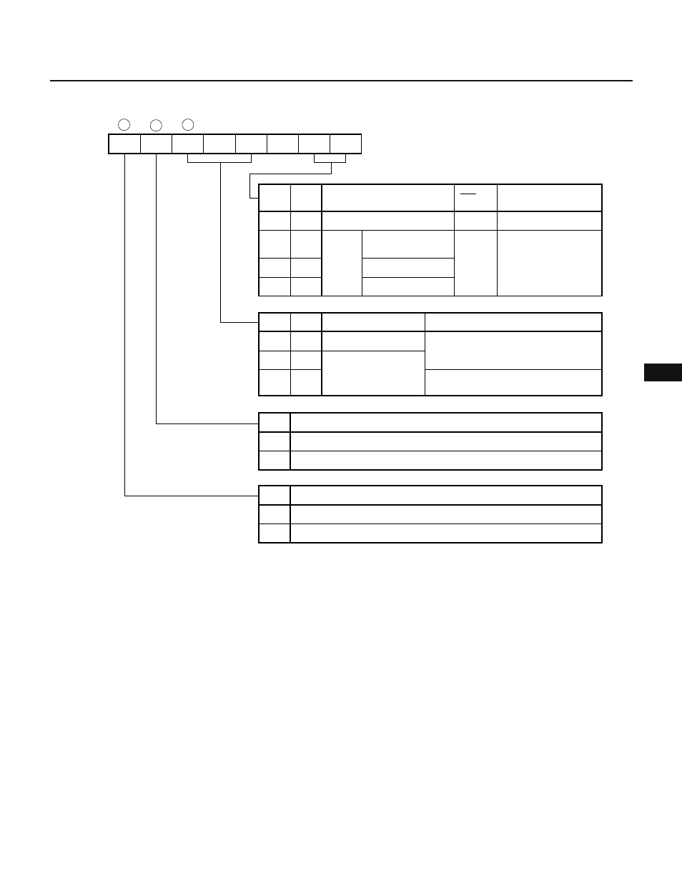
Fig. 10-10 Format of Clock Synchronous Serial Interface Mode Register (CSIM)
Caution Do not change CTXE from 0 to 1 or CRXE from 1 to 0, or vice versa, by means of a single instruction. If this is attempted, the serial
clock counter will malfunction and the first communication after the change will be terminated before the eighth bit is sent. To
change those statuses, use two instructions as shown below:
Example Changing CTXE from 1 to 0 and CRXE from 0 to 1
CLR1 CTXE
SET1 CRXE
CTXE
7
CRXE
6
WUP
5
0
4
MOD1
3
0
2
CLS1
1
CLS0
0
CSIM
CLS1
Internal
clock
External clock
Selects serial clock
0
0
CLS0
0
1
SCK pin
Master/slave selection in
SBI mode
8-bit timer/counter 3
output/2
Input
1
0
1
1
f
CLK
/32
f
CLK
/8
Input
Slave
Master
WUP
3-wire serial I/O mode
Operation mode
0
0
MOD1
0
1
Controls wakeup function
SBI mode
1
1
Generates interrupt request at
each serial transfer
Generates interrupt request only
when address is received
CRXE
Disabled
Reception
0
1
Enabled
CTXE
Disabled
Transmission
0
1
Enabled
(00H when RESET is input)