NEC PD78214 User Manual
Page 225
196
µ
PD78214 Sub-Series
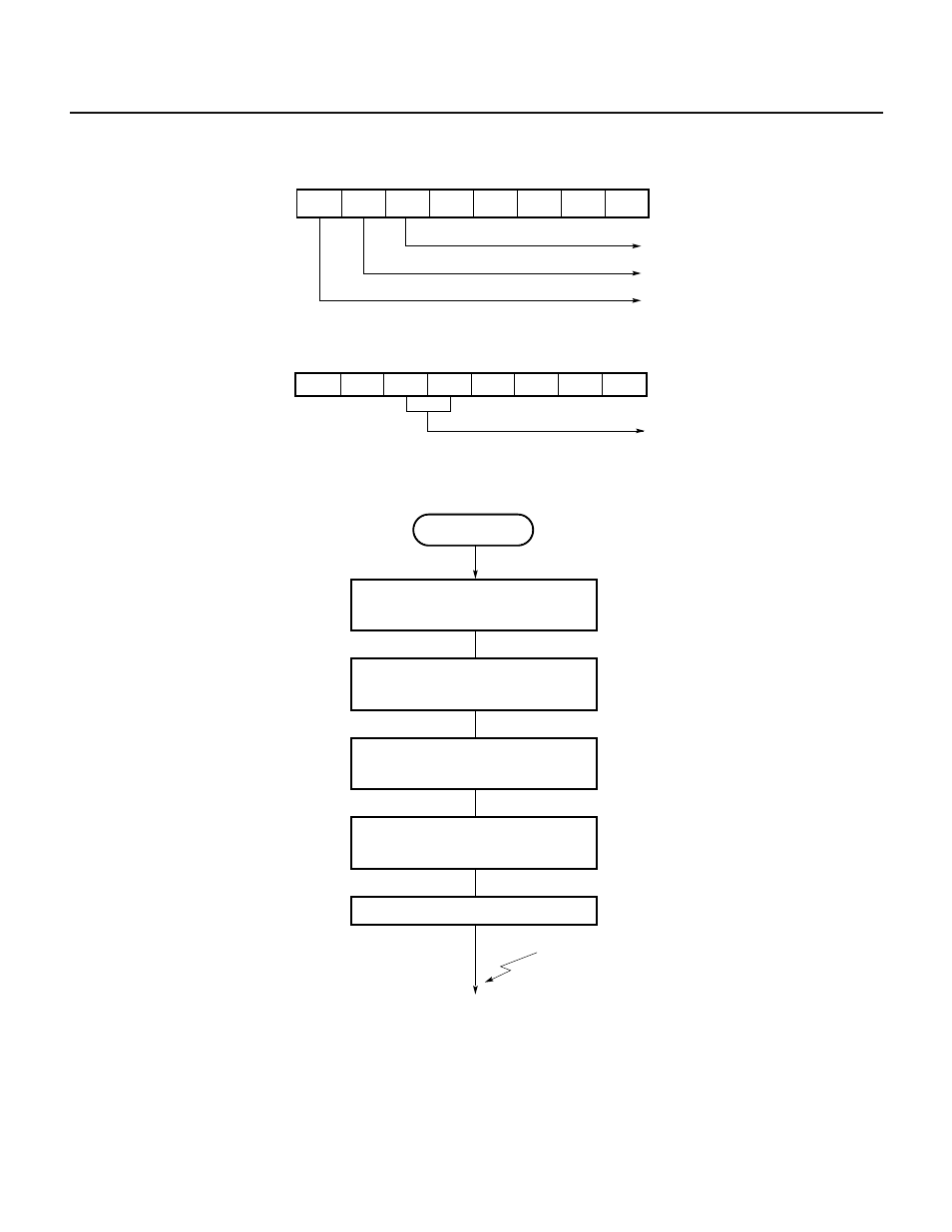
(c) Timer control register 1 (TMC1)
(d) External interrupt mode register 0 (INTM0)
Fig. 7-105 Setting Procedure for Pulse Width Measurement
Set CRC1 register
Set INTM0 register and
MK0L register
CRC2
←10H
X
0
←0
Initialize buffer memory for capture value
Enable interrupt
INTP1 interrupt
; Specifies valid edge of
INTP1 input to be both
edges and unmasks interrupt
Pulse width
measurement
Set TMC1 register
; Sets bit 7 of TMC1 to 1
Sets normal mode (CMD2 = 0)
CE2
←1
CMD2
←0
7
6
5
4
3
2
1
0
1
0
0
0
×
0
0
TMC1
×
Normal mode
Overflow flag
Enables counting
7
INTM0
0
1
6
5
4
3
2
1
0
Ч
Ч
Specifies valid edge of INTP1 input
to be rising and falling edges
Ч
1
Ч
Ч