3 i/o circuits and unused-pin handling, Chapter 2 pin functions – NEC PD78214 User Manual
Page 62
33
Chapter 2 Pin Functions
2
2.3 I/O CIRCUITS AND UNUSED-PIN HANDLING
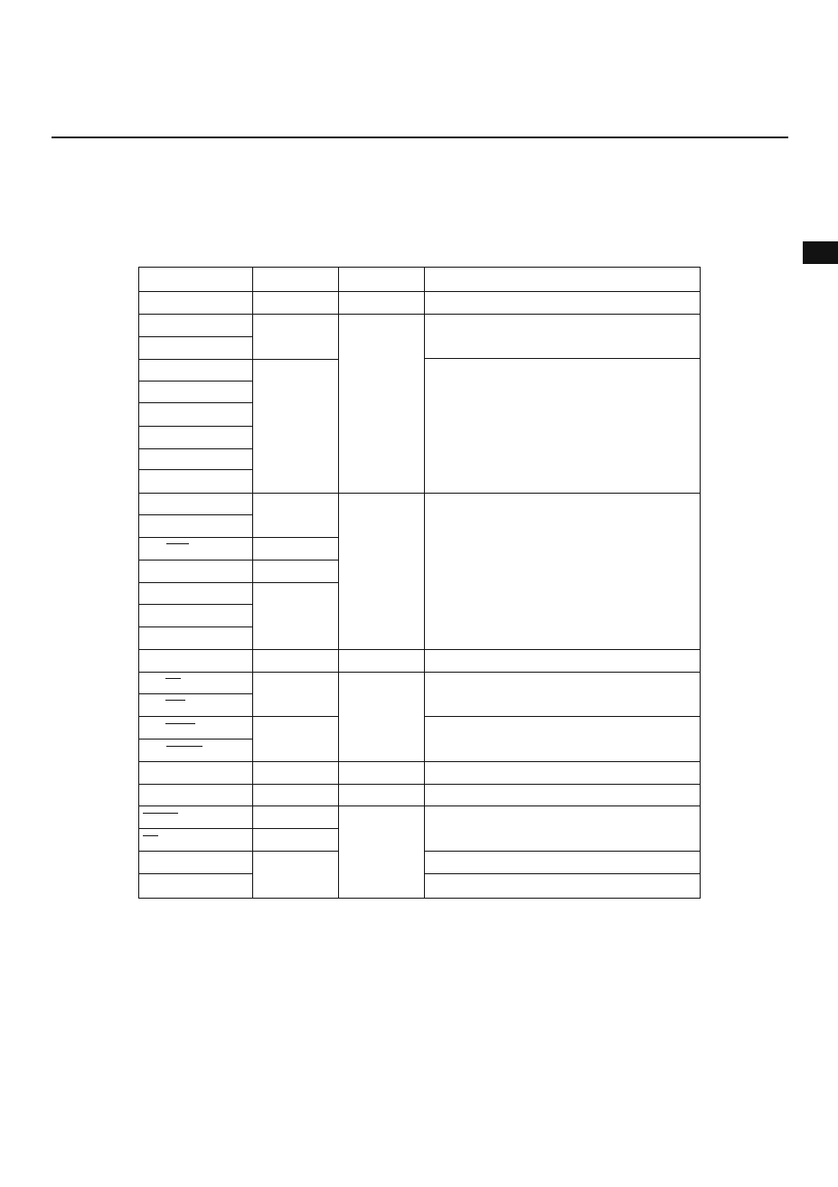
Table 2-4 lists the types of I/O circuits provided for each pin and describes how pins are handled when not used.
Fig. 2-1 illustrates the I/O circuit types.
Table 2-4 Types of I/O Circuits and Unused-Pin Handling
P00-P07
P20/NMI
P21/INTP0
P22/INTP1
P23/INTP2/CI
P24/INTP3
P25/INTP4/ASCK
P26/INTP5
P27/SI
P30/RxD
P31/TxD
P32/SCK
P33/SB0/SO
P34/TO0-P37/TO3
P40/AD0-P47/AD7
P50/A8-P57/A15
P60/A16-P63/A19
P64/RD
P65/WR
P66/WAIT/AN6
P67/REFRQ/AN7
P70/AN0-P75/AN5
ASTB
RESET
EA
AV
REF
AV
SS
Pin
Input/output
Recommended unused-pin handling
Leave open.
Type of I/O circuit
4
Output
2
5-A
8-A
10-A
2-A
5-A
4
5-A
11
9
4
2
1
—
Connect to V
DD
or V
SS
.
Connect to V
DD
.
Leave open.
Connect to V
DD
when used as an input pin.
Leave open when used as an output pin.
Connect to V
DD
when used as an input pin.
Leave open when used as an output pin.
Connect to V
DD
Note
when used as an input pin.
Leave open when used as an output pin.
Connect to V
SS
.
Leave open.
Connect to V
DD
or V
SS
Note
.
Connect to V
SS
.
Input
Input/output
Output
Input/output
Input
Output
Input
Note See Section 8.6.
Remark Since the type numbers of I/O circuits are numbered in the 78K series, they may not be serial in a certain product. (A product may
not contain some of these I/O circuits.)
Caution When an I/O pin is used as both an input and output pin, connect the pin to the V
DD
pin through a resistor of less than 100 kilohms.
(Especially, when the RESET pin goes to a voltage higher than the low level upon power on, or when an I/O pin is switched with
software.)
—