4 built-in pull-up resistor – NEC PD78214 User Manual
Page 111
82
µ
PD78214 Sub-Series
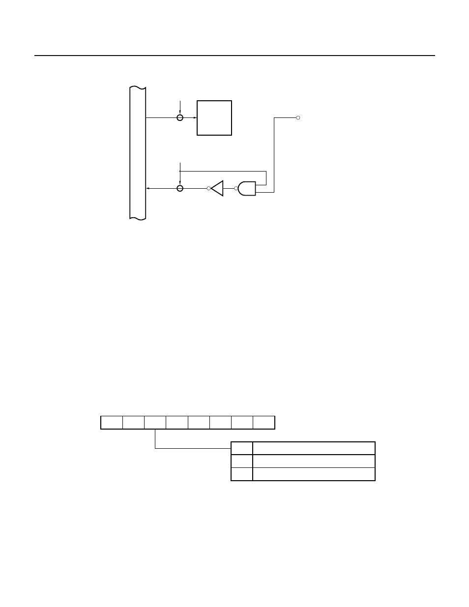
Fig. 5-30 Port Specified as an Input Port
Caution Although its ultimate purpose is to manipulate only 1 bit, a bit manipulation instruction accesses a port in 8-bit units. If a bit
manipulation instruction is used for a port some pins of which are in the output mode and the other pins of which are in the input
mode, the contents of the output latch corresponding to the pin in the input mode become undefined (except for the bits
manipulated by the SET1 or CLR1 instruction). Special care should be taken if bits are switched between the input and output
modes.
The same holds true when the port is manipulated using 8-bit arithmetic/logical instructions.
(3) Address bus (A8 through A15)
Port 5 is used as the address bus automatically for external addresses. Do not execute I/O instructions for port 5.
5.6.4 Built-In Pull-Up Resistor
Port 5 has built-in pull-up resistors. When port 5 must be pulled up, the built-in pull-up resistors should be used.
Use of the built-in pull-up resistors can reduce the number of the required components and the required
installation space.
Use of a built-in pull-up resistor can be specified for each pin of port 5, independently of the other pins, by the PUO5
bit of pull-up-resistor-option register (PUO) and the port 5 mode register (PM5).
When the PUO5 bit is 1, the built-in pull-up resistor for a pin specified by the PM5 (PM5n = 1, n = 0 to 7) is connected.
Fig. 5-31 Pull-Up-Resistor-Option Register Format
0
7
PUO6
6
PUO5
5
PUO4
4
PUO3
3
PUO2
2
0
1
0
0
PUO
PUO5
Connected with port 5
Not connected with port 5
Specifies pull-up resistor connection of port 5
(00H when RESET is input)
0
1
Caution For the
µPD78213, port 5 is used as an address bus. Therefore, the PUO5 bit must be kept to be 0, and a built-in pull-up resistor must
not be connected. For the
µPD78214, the same conditions must be maintained if port 5 is used as an address bus.
Remark Resetting the PUO to 00H can reduce the required current in the STOP mode.
Internal bus
WR
PORT
P5n
n = 0 to 7
Output
Iatch
RD
IN