Chapter 7 timer/counter units – NEC PD78214 User Manual
Page 210
181
Chapter 7 Timer/Counter Units
7
(1) Basic operation
By setting ENTOn (n = 2, 3) of the timer output control register (TOC) to 1, the timer outputs (TO2, TO3) can
be changed with the timing determined by MOD0, MOD1, and CLR21 of capture/compare control register 2
(CRC2).
In addition, by clearing ENTOn (n = 2, 3) to 0, the levels of the timer outputs (TO2, TO3) can be tied. The level
where an output is tied is determined by ALVn (n = 2, 3) of the timer output control register (TOC). When ALVn
(n = 2, 3) is 0, the output is tied high; when ALVn (n = 2, 3) is 1, the output is tied low.
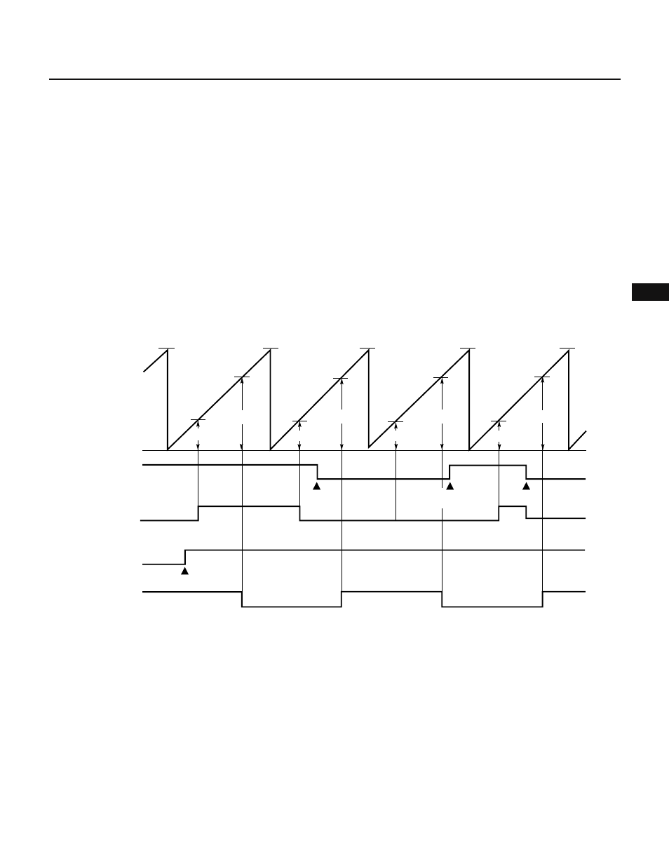
(2) Toggle output
Toggle output is an operation mode where the level of output is inverted each time the value of a compare
register (CR20, CR21) coincides with the value of 8-bit timer 2 (TM2). The output level of TO2 is inverted when
the value of CR20 coincides with the value of TM2. The output level of TO3 is inverted when the value of CR21
coincides with the value of TM2.
When 8-bit timer/counter 2 is stopped by resetting the CE2 bit of the TMC1 register to 0, the output level present
at that time is held.
Fig. 7-84 Toggle Output Operation
FFH
TM0
count value
0H
ENTO0
Value of CR20
Value of CR21
Instruction
execution
Instruction execution
ENTO3
Output of TO2
(ALV2 = 1)
Output of TO3
(ALV3 = 0)
Value of CR21
Value of CR20
Instruction
execution
Instruction
execution
Value of CR20
Value of CR21
Value of CR20
Value of CR21
FFH
FFH
FFH
FFH