4 built-in pull-up resistor – NEC PD78214 User Manual
Page 103
74
µ
PD78214 Sub-Series
(3) Control signal input or output
Regardless of setting of the port mode 3 register (PM3), each bit of port 3 can be used to input or output a
control signal, independently of the other bits, by setting the corresponding bit of the port mode control
register (PMC3) to 1. When a pin is used for a control signal, executing a read instruction for the port can detect
the state of the control signal.
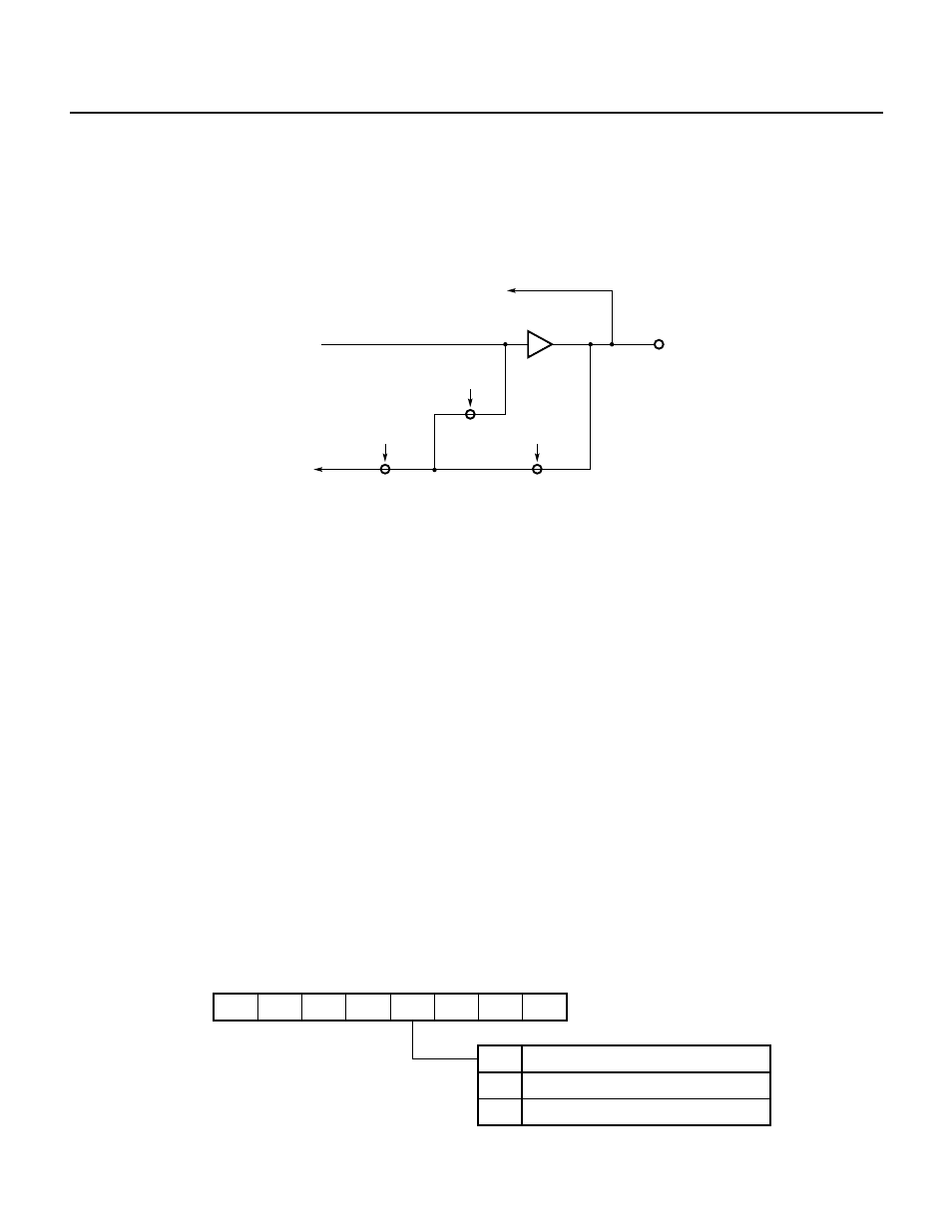
Fig. 5-18 Port Specified as a Control Signal Input or Output
(a) Control signal output
When a bit of the port mode register (PM3n) is 1, executing a read instruction for port 3 can read the level
of the corresponding control signal pin.
When a bit of the port mode register (PM3n) is 0, executing a read instruction for port 3 can check the
corresponding control signal in the
µPD78214.
Remark For bit 3 (P33) of port 3, “SB0” is a reserved word in the NEC assembly program package. The bit is also defined in a header
file named sfrbit.h by the C compiler.
(b) Control signal input
Only when a bit of the port mode register (PM3n) is 1, executing a read instruction for port 3 can read the
level of the corresponding control signal pin.
5.4.4 Built-In Pull-Up Resistor
Port 3 has built-in pull-up resistors. When port 3 must be pulled up, the built-in pull-up resistors should be used.
Use of the built-in pull-up resistors can reduce the number of the required components and the required
installation space.
Use of a built-in pull-up resistor can be specified for each bit of port 3, independently of the other bits, by the PUO3
bit of pull-up-resistor-option register (PUO) and the port 3 mode register (PM3). When the PUO3 bit is 1, the built-
in pull-up resistor for a pin specified by the PM3 (PM3n = 1, n = 0 to 7) is connected.
If a pin is specified to be in the control mode, the built-in pull-up resistor for the pin is connected. (A built-in pull-
up resistor is connected to a pin that becomes an output pin during the control mode.) If you do not want to use
the built-in pull-up resistor for a pin in the control mode, reset the corresponding bit of the PM3 to 0 (output mode).
Fig. 5-19 Pull-Up-Resistor-Option Register Format
Remark Resetting the PUO2 bit to 00H can reduce the required current in the STOP mode.
0
7
PUO6
6
PUO5
5
PUO4
4
PUO3
3
PUO2
2
0
1
0
0
PUO
PUO3
Connected with port 3
Not connected with port 3
Specifies pull-up resistor connection of port 3
(00H when RESET is input)
0
1
RD
PM3n = 1
PM3n = 0
PM3n
n = 0 to 7
Control (input)
Control (output)
Internal bus