3 operation, Chapter 5 port functions – NEC PD78214 User Manual
Page 102
73
Chapter 5 Port Functions
5
5.4.3 Operation
Port 3 is an I/O port. Its pins also function as control signal pins.
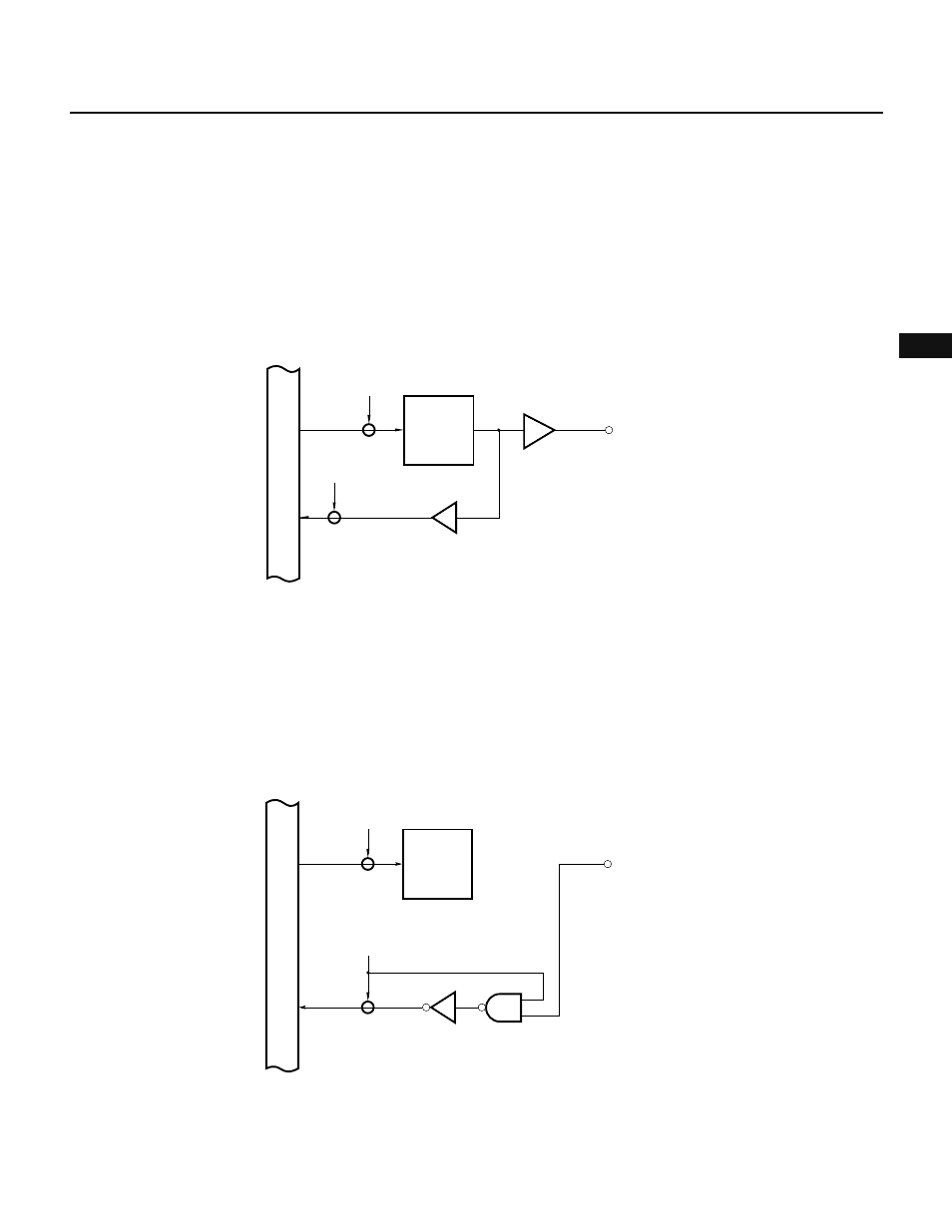
(1) Output port
When port 3 is in the output mode, its output latch is operable. Once the output latch becomes operable, data
can be transferred between the output latch and the accumulator using a transfer instruction. The output latch
can be loaded with any data by a logical operation instruction. Once the output latch is loaded with some data,
it retains the data until it is loaded
Note
with other data.
Note This includes a case in which any other bit of the same port is manipulated using a bit manipulation instruction.
Fig. 5-16 Port Specified as an Output Port
Caution
Although its ultimate purpose is to manipulate only 1 bit, a bit manipulation instruction accesses a port in 8-bit units. If a
bit manipulation instruction is used for a port some pins of which are in the output mode and the other pins of which are in
the input mode, the contents of the output latch corresponding to the pins in the input mode or the control mode become
undefined (except for the bits manipulated by the SET1 or CLR1 instruction). Special care should be taken if bits are switched
between the input and output modes.
The same holds true when the port is manipulated using 8-bit arithmetic/logical instructions.
(2) Input port
The level of each pin of port 3 can be transferred to the accumulator by a transfer instruction. Also in this case,
data can be written to the output latches, and all output latches store data transferred from the accumulator
by a transfer instruction or other similar instruction, regardless of the current mode of the port operation. If
a pin is specified as an input port, however, the latched data is not output to the port pin because the output
buffer at the pin is in the high-impedance state. (When the pin is switched to the output mode, the contents
of the output latch are output to the port pin.) If a pin is specified as an input port, the contents of the output
latch for the pin cannot be transferred to the accumulator.
Fig. 5-17 Port Specified as an Input Port
P3n
n = 0 to 7
Internal bus
WR
PORT
RD
OUT
Output
Iatch
Internal bus
WR
PORT
P3n
n = 0 to 7
Output
Iatch
RD
IN