1 hardware configuration, 2 setting the i/o mode and control mode – NEC PD78214 User Manual
Page 105
76
µ
PD78214 Sub-Series
5.5.1 Hardware Configuration
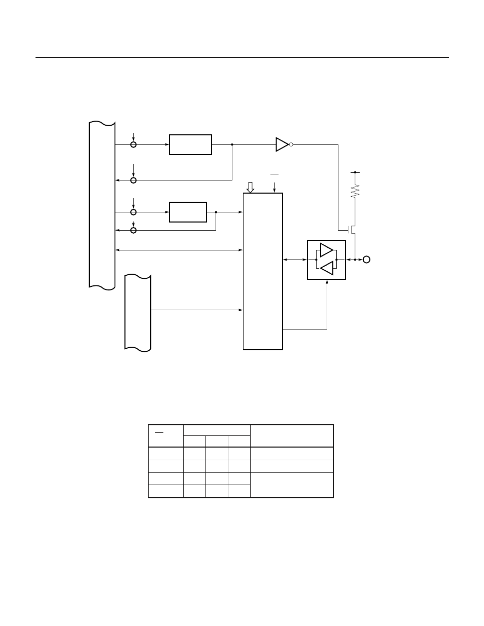
Fig. 5-21 shows the hardware configuration of port 4.
Fig. 5-21 Block Diagram of Port 4
5.5.2 Setting the I/O Mode and Control Mode
The memory expansion mode register (MM, see Fig 13-1) specifies the operating mode of port 4, as listed in Table
5-5.
Table 5-5 Port 4 Operating Modes
1
1
1
0
0
0
1
×
MM2
0
0
1
×
MM1
0
1
1
×
MM0
EA pin
MM register bit
Operation mode
Input port
Output port
Address/data bus
(AD0-AD7)
For the
µPD78213, port 4 functions only as the address/data bus (AD0 through AD7).
Internal data bus
WR
PUO
Pull-up resistor option register
PUO4
WR
P4n
RD
P4n
RD
PUO
Output latch
P4n
n = 0 to 7
V
DD
MM0-MM2 EA
Internal address bus
I/O control circuit
P4n