Chapter 2 pin functions, 1 pin function list, 1 normal operating mode – NEC PD78214 User Manual
Page 54
25
2
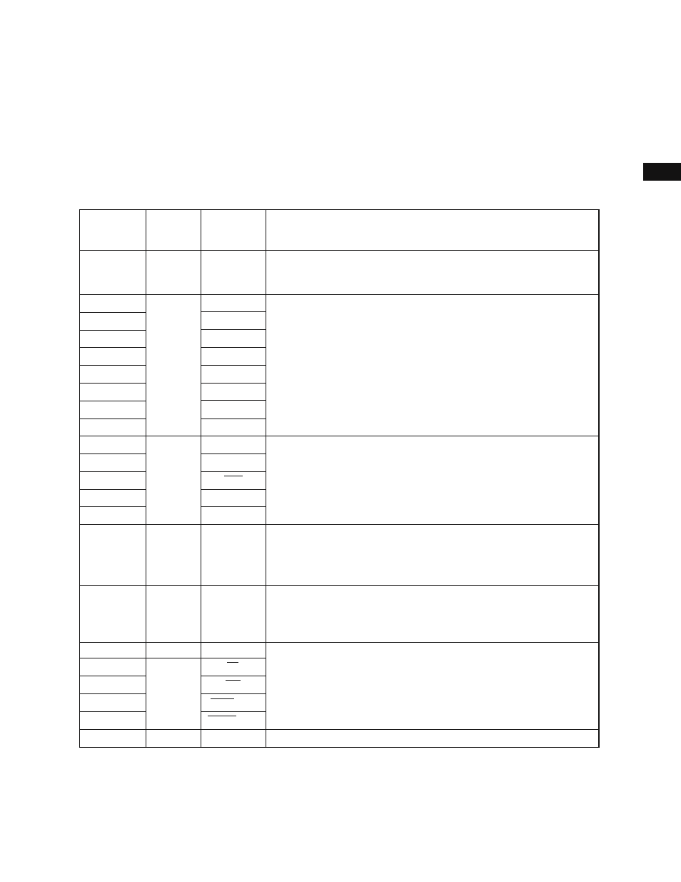
CHAPTER 2 PIN FUNCTIONS
2.1 PIN FUNCTION LIST
2.1.1 Normal Operating mode
(1) Ports
P20
P21
P22
P23
P24
P25
P26
P27
P30
P31
P32
P33
P34-P37
P60-P63
P64
Note 2
P65
Note 2
P66
P67
P70-P75
Port 0 (P0):
Can be used as two four-bit, real-time output ports. Can drive transistors
directly.
Port 2 (P2):
Cannot be used as a general-purpose port (non-maskable interrupt). The
input level can be checked as part of the interrupt routine. Pins P22 to
P27 can be collectively connected to internal pull-up resistors by means
of software.
Port 3 (P3):
Each pin can be assigned to be either an input or output pin. Input pins
can be collectively connected to internal pull-up resistors by means of
software.
Port 4 (P4):
Can be simultaneously assigned to be either input or output pins. Can be
collectively connected to internal pull-up resistors by means of software.
Can directly drive LEDs.
Port 5 (P5):
Each pin can be assigned to be either an input or output pin. Input pins
can be collectively connected to internal pull-up resistors by means of
software. Can directly drive LEDs.
Port 6 (P6):
Each of pins P64 to P67 can be assigned to be either an input or output
pin. Input pins P64 to P67 can be collectively connected to internal pull-
up resistors by means of software.
Port 7 (P7)
Output
Input
NMI
INTP0
INTP1
INTP2/CI
INTP3
INTP4/ASCK
INTP5
SI
RxD
TxD
SCK
SO/SB0
TO0-TO3
A16-A19
RD
WR
WAIT/AN6
REFRQ/AN7
AN0-AN5
—
Pin name for
secondary
function
Notes 1. In the case of the
µPD78213, these pins do not function as ports.
2. In the case of the
µPD78213, neither P64 nor P65 functions as a port.
Pin
Function
Input/Output
Input
Input/Output
Input/Output
Input/Output
Input/Output
Output
P00-P07
P40-P47
Note 1
P50-P57
Note 1
A8-A15
AD0-AD7