Chapter 7 timer/counter units – NEC PD78214 User Manual
Page 186
157
Chapter 7 Timer/Counter Units
7
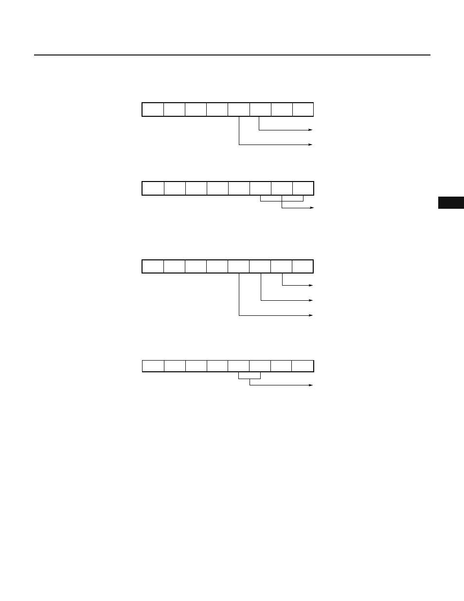
Fig. 7-63 Setting of Control Registers for Pulse Width Measurement
(a) Timer control register 1 (TMC1)
(b) Prescaler mode register 1 (PRM1)
(c) Capture/compare control register 1 (CRC1)
(d) External interrupt mode register 0 (INTM0)
7
6
5
4
3
2
1
0
0
0
1
0
0
CRC1
Disables clearing TM1, when TM1
coincides with CR10
Specifies the CR11 register as a capture
register
Clearing TM1, when TM1 is captured to
CR11, is disabled
0
0
0
7
6
5
4
3
2
1
0
0
0
0
0
1
TMC1
Overflow flag
Enables counting TM1
Ч
Ч
Ч
7
6
5
4
3
2
1
0
PRS10
0
PRM1
Ч
Ч
Ч
PRS12 PRS11
×
Specifies count clock
(x/f
CLK
; where x = 16, 32, 64,
128, 256, or 512)
7
INTM0
0
1
6
5
4
3
2
1
0
Ч
Ч
Ч
Specifies valid edge of INTP0 input
to be rising and falling edges
× : Don't care
Ч
Ч
1