5 notes, 1 common notes on all timers/counters – NEC PD78214 User Manual
Page 241
212
µ
PD78214 Sub-Series
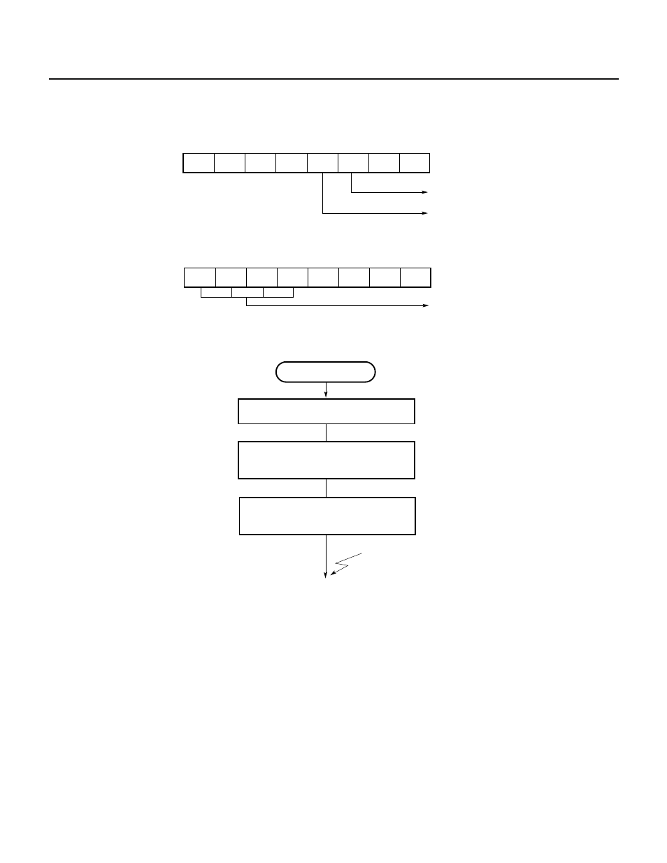
Fig. 7-130 Setting of Control Registers for Interval Timer Operation
(a) Timer control register 0 (TMC0)
(b) Prescaler mode register 0 (PRM0)
7
6
5
4
3
2
1
0
PRS3
0
0
0
0
PRM0
PRS2
PRS1
PRS0
Specifies count clock
(x/f
CLK
; where x = 16, 32, 64, 128, 256, or 512)
Fig. 7-131 Setting Procedure for Interval Timer Operation
7.5 NOTES
7.5.1 Common Notes on All Timers/Counters
(1) When the registers listed below are rewritten while a counter is operating (with the CEm bit of register TMCn
is set), the counter can malfunction. The cause of such a malfunction is that when a hardware function change
made by the rewriting of a register conflicts with a state change of the function before the rewriting, which
change is to have priority is undefined.
Before rewriting these registers, be sure to stop counter operation for safety.
• Prescaler mode register (PRMn)
• Capture/compare control register (CRCn)
• Timer output control register (TOC)
• CMD2 bit of timer control register 1 (TMC1)
★
Interval timer
Set count value in CR30 register
Start counting
; Sets bit 7 of TMC0 to 1
INTC30 interrupt
CE
←1
CR30
←n
Set PRM0 register
7
6
5
4
3
2
1
0
0
0
0
0
0
0
1
TMC0
Overflow flag
Enables counting TM0
Ч