2 port 0 – NEC PD78214 User Manual
Page 89
60
µ
PD78214 Sub-Series
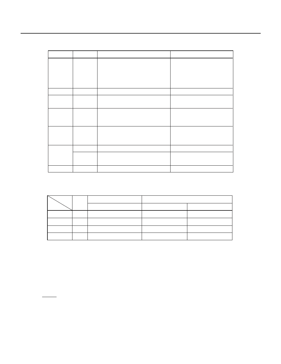
Table 5-1 Port Functions
Port 0
Port 2
Port 3
Port 4
Note
Port 5
Note
Port 6
Note
Port 7
Software-specified pull-up resistor
Name
Pin name
P00-P07
P20-P27
P30-P37
P40-P47
P50-P57
P60-P63
P64-P67
P70-P75
Function
Can be specified for either output in 8-bit
units or high impedance.
Can also function as 4-bit real-time
output port (P00-P03 and P04-P07).
Can drive transistors directly.
Input port
Can be specified for either input or
output in bit units.
Can be specified for either input or
output in 8-bit units
Can drive LEDs directly.
Can be specified for either input or
output in bit units
Can drive LEDs directly.
Output port
Can be specified for either input or
output in bit units
Input port
Input port
I/O port
Output port
Total
6 (6)
28 (10)
—
34 (16)
—
16 (0)
0 (0)
16 (0)
—
0 (0)
8 (8)
8 (8)
Software-specified pull-up resistors
Directly driven LEDs
Direct driven transistor
I/O
Port
Input mode
Output mode
Total
In 6-bit units (P22-P27)
For all input pins at a time
In 8-bit units
For all input pins at a time
—
For all input pins at a time
—
—
14 (14)
28 (10)
12 (12)
54 (36)
Note For
µPD78213, P40 through P47, P50 through P57, P64, or P65 does not function as ports.
Table 5-2 Number of I/O Ports
Values enclosed in parentheses apply to the
µ
PD78213.
5.2 PORT 0
Port 0 is an 8-bit output-only port with an output latch and can drive transistors directly. The port 0 mode register
(PM0) can specify that port 0 be in either the output mode or high-impedance state in 8-bit units.
A set of P00 through P03 and a set of P04 through P07 function as a 4-bit real-time output port. Similarly, a set of
P00 through P07 functions as an 8-bit real-time output port. These ports can output the contents of the P0L and
P0H buffers at arbitrary intervals. The real-time output trigger control register (RTPC) specifies whether port 0 is
to function as an ordinary output port or real-time output port.
When the RESET signal is input, the output of port 0 becomes high impedance, and the contents of the output latch
become undefined.