2 note, Chapter 15 reset function – NEC PD78214 User Manual
Page 422
393
Chapter 15 Reset Function
15
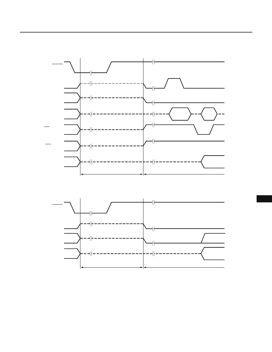
Fig. 15-3 Timing Charts for Reset Operation
(a) For
µPD78213
(b) For
µPD78214
15.2 NOTE
When resetting the system at power-on, do not set the RESET signal high immediately after the supply voltage
reaches the specified level. Keep the signal low until oscillation has settled.
★
Reset period
Hi-Z
Hi-Z
Hi-Z
Hi-Z
Hi-Z
Hi-Z
Address
(output)
Program
(input)
RESET
(input)
ASTB (output)
A8-A19
(output)
AD0-AD7
RD (output)
WR output
Other I/O ports
Instruction execution period after reset
Reset period
Hi-Z
Hi-Z
Hi-Z
RESET
(input)
ASTB (output)
P60-P63
(output)
Other I/O ports
Instruction execution period after reset