6 sample applications, Chapter 7 timer/counter units – NEC PD78214 User Manual
Page 180
151
Chapter 7 Timer/Counter Units
7
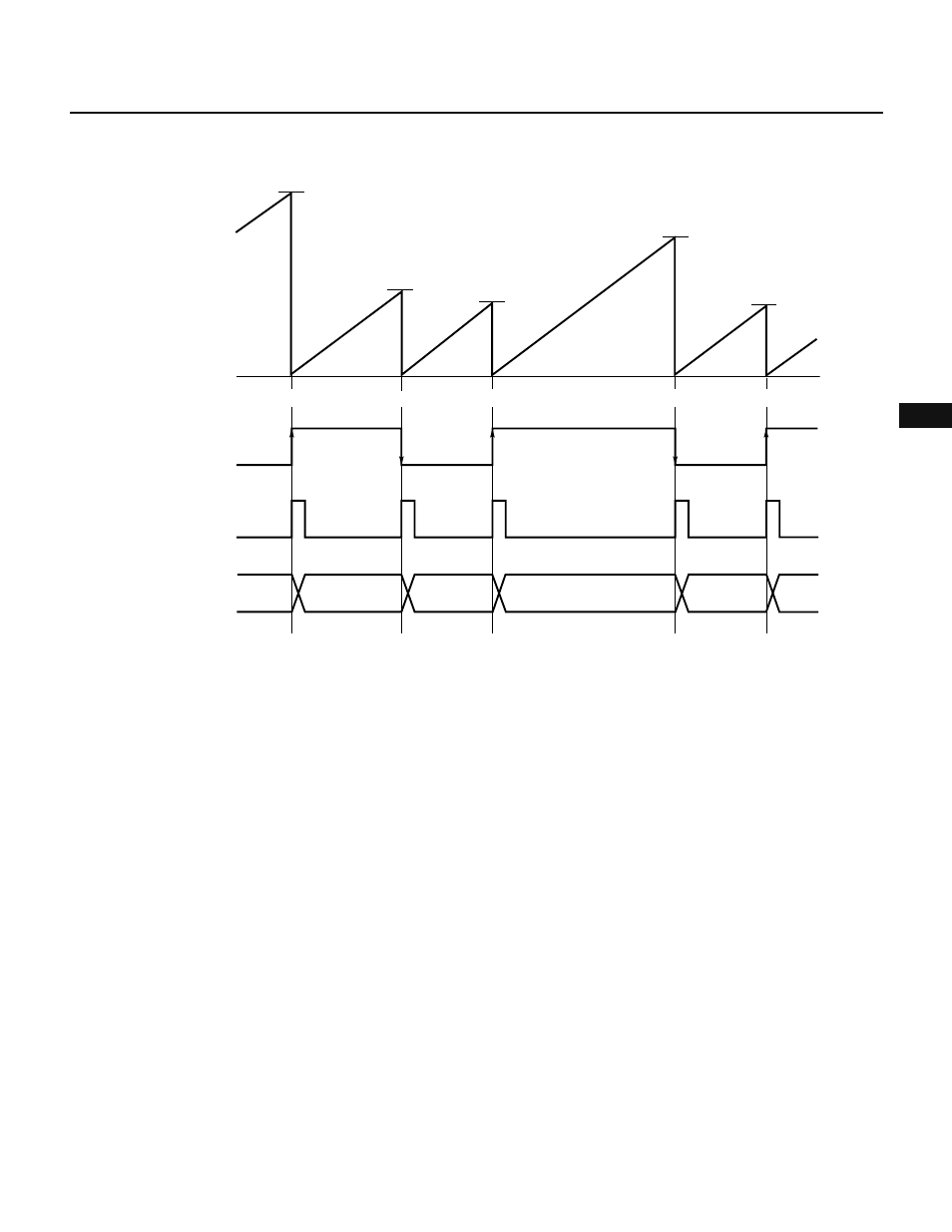
Fig. 7-54 TM1 Cleared after Capture Operations
Remark
D
n
: TM1 count value (n = 0, 1, 2, ...)
CLR10 = 0, CLR11 = 0, CM = 1
7.2.6 Sample Applications
(1) Interval timer operation (1)
By free running 8-bit timer 1 (TM1), and adding a value to a compare register (CR10, CR11) in an interrupt
handling routine, 8-bit timer/counter 1 can be used as an interval timer whose period is as long as the added
value. (See Fig. 7-55.)
In addition, 8-bit timer 1 (TM1) has two compare registers, so that interval timers with two types of periods
can be produced.
Fig. 7-56 shows the setting of control registers. Fig. 7-57 shows the setting procedure. Fig. 7-58 shows
interrupt handling.
N3
N2
N4
N5
N1
0H
TM1
count value
Captured
Captured
Captured
Captured
N1
N2
N3
N4
INTP0
pin input
INTP0
interrupt request
Capture/compare
register (CR11)
Captured