NEC PD78214 User Manual
Page 153
124
µ
PD78214 Sub-Series
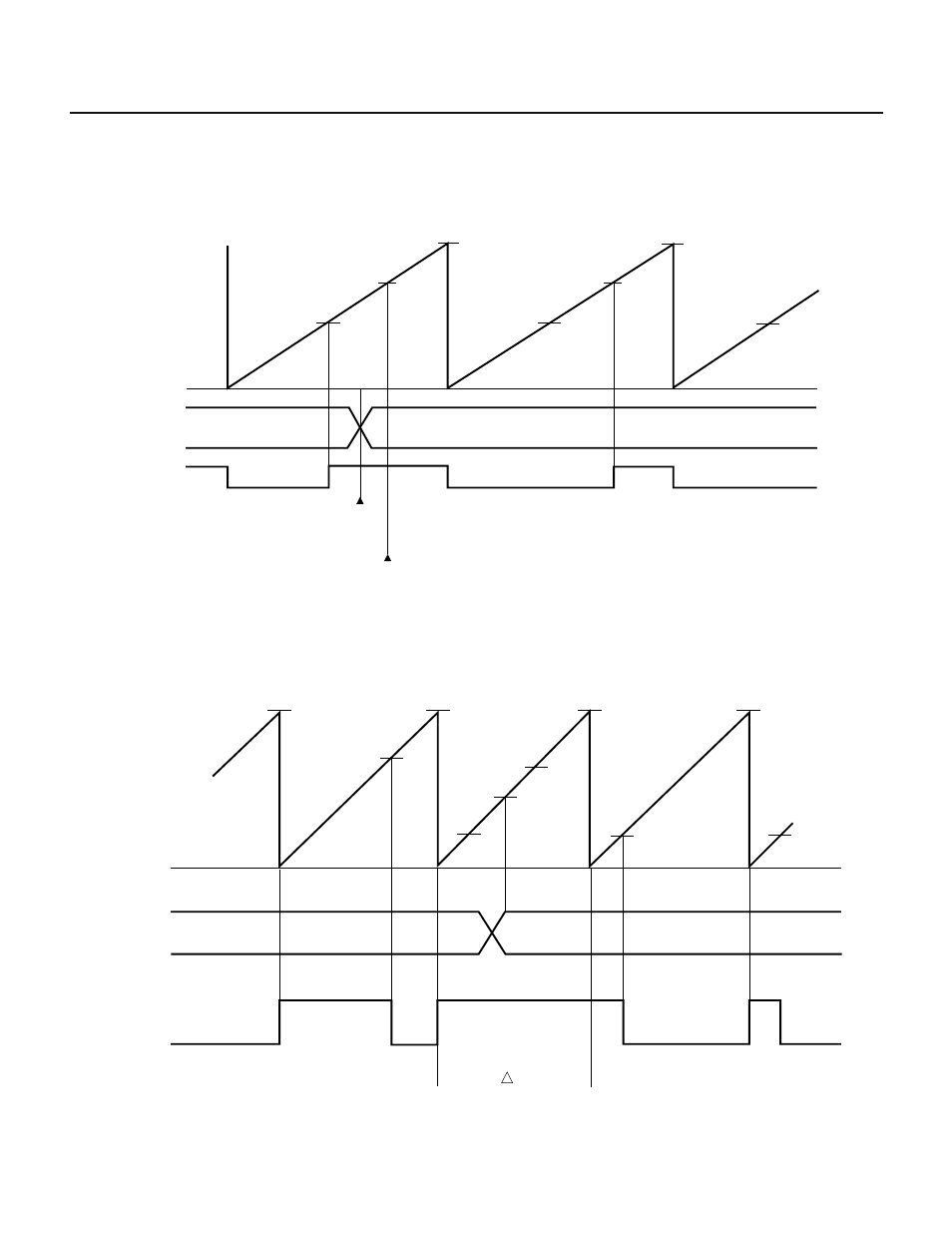
Even if the value of a compare register (CR00, CR01) coincides with the value of 16-bit timer 0 (TM0) more than
once during one period of PWM output, the output levels on the timer outputs (TO0, TO1) do not change.
Fig. 7-16 Example of Rewriting Compare Register CR00
TO0
T1
T2
T1
T1
T1
T2
T2
FFFFH
FFFFH
TM0
count value
0H
CR00
Rewriting
CR00
TO0 does not change though CR00 coincides with TM0
Cautions 1. If a value less than the value of 16-bit timer 0 (TM0) is set in a compare register (CR00, CR01), a PWM signal with a 100% duty
factor is output. Rewrite the CR00 or CR01 compare register, if required, by using an interrupt generated by a coincidence
between TM0 and the compare register.
Fig. 7-17 Example of PWM Output Signal with a 100% Duty Factor
TO0
FFFFH
CR00
0H
n1
n2
n2
n2
n2
n3
n1
FFFFH
FFFFH
FFFFH
TM0
count value
When a value, n2 less than TM0 value, n3 is written to CR00
here, the duty factor is 100% during this period.
n1
Remark ALV0 = 0