8 ppg output, Chapter 7 timer/counter units – NEC PD78214 User Manual
Page 154
125
Chapter 7 Timer/Counter Units
7
2. If timer output is disabled (ENTOn = 0: n = 0, 1), the output level on the TOn (n = 0, 1) pin is the inverted value of the value set
in ALVn (n = 0, 1). Accordingly, note that if timer output is disabled when the PWM output function is selected, the active level
is output.
7.1.8 PPG Output
The PPG output function outputs a square wave that has a period determined by the CR01 compare register, and
has a pulse width determined by the CR00 compare register. PPG output is PWM output whose period is made
variable. This output signal can be output on the TO0 pin only.
Before this function can be used, the CLR01 bit of capture/compare control register 0 (CRC0) must be set to 1.
The pulse period and pulse width are as follows:
• PPG period = ((value set in CR01 compare register) + 1)
× 8/f
CLK
• PPG pulse width = ((value set in CR00 compare register)
× 8 + 2)/f
CLK
(value set in CR00)
× 8/f
CLK
where, CR00
≤ CR01
• Duty factor = (PPG pulse width)/(PPG period) = ((value set in CR00)
× 8 + 2)/(((value set in CR01) + 1) × 8) (value
set in CR00)/((value set in CR01) + 1)
Caution In PPG output, the actual pulse width is longer than a value obtained with the approximate expression by two clock pulses of f
CLK
for the active level, and is shorter than such an approximate value by two clock pulses of f
CLK
for the inactive level. Take this point
into consideration when high-precision output is required or the PPG pulse period is short.
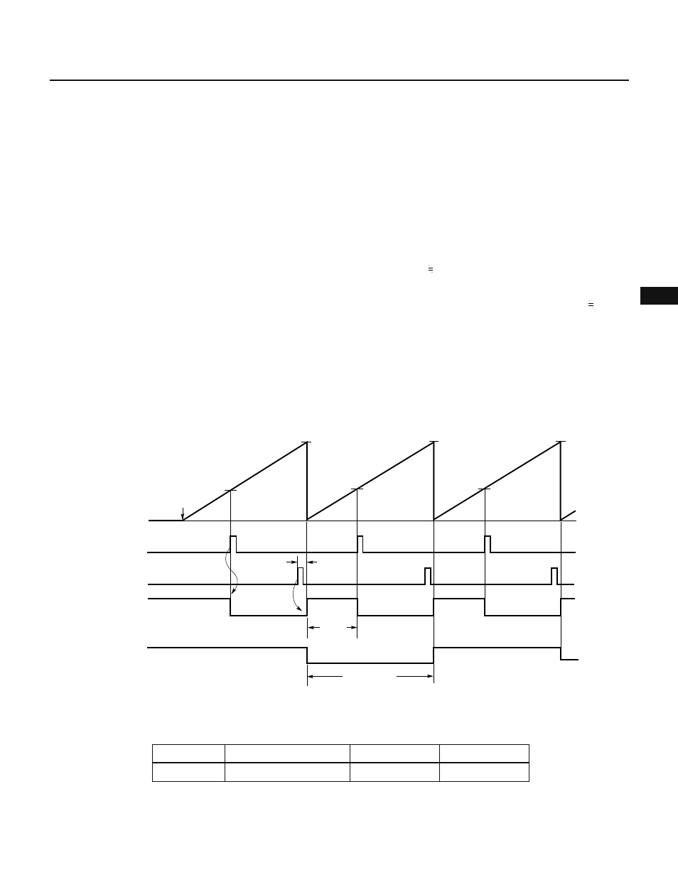
Fig. 7-18 shows an example of PPG output using 16-bit timer 0. Fig. 7-19 shows an example of PPG output when
CR00 = CR01. Fig. 7-20 shows an example of PPG output when CR00 = 0000H.
Fig. 7-18 Example of PPG Output Using TM0
Remark ALV0 = 0, ALV1 = 0
Table 7-8 PPG Output on TO0 (f
CLK
= 6 MHz)
Count clock
f
CLK
/8
Minimum pulse width
Note
1.3
µs
PPG period
2.6
µs -87.4 ms
PPG frequency
385 kHz-11.4 Hz
Note The case where CR00 = 0 is excluded.
CR01
INTC00
Count starts
CR01
CR01
CR00
CR00
CR00
INTC01
TO0
(PPG output)
TO1
(timer output)
Pulse period
Pulse
width
T
TM0
count value
0H