NEC PD78214 User Manual
Page 141
112
µ
PD78214 Sub-Series
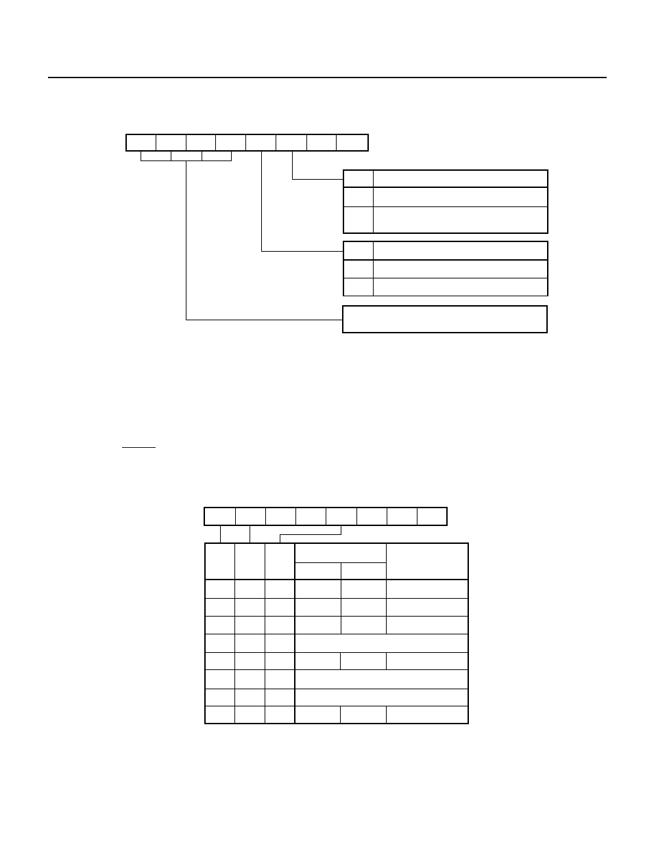
Fig. 7-3 Format of Timer Control Register 0 (TMC0)
7
6
5
4
3
2
1
0
CE3
0
0
0
CE0
OVF0
0
0
TMC0
OVF0
0
1
1
0
CE0
TM0 overflow flag
Overflow does not occur
Overflow occurs (countiing up from
FFFFH to 0000H)
TM0 counting control
Clears and stops counting
Enables counting
These bits control counting for 8-bit timer/
counter 3 (see Fig. 7-123).
Remark
The OVF0 bit can be reset only by software.
(2) Capture/compare control register 0 (CRC0)
The CRC0 register is used to specify the condition for enabling the clear operation of TM0 to be performed
by a coincidence between the value of the CR01 compare register and the count value of TM0. The CRC0
register is also used to specify a timer output (TO0, TO1) mode.
The CRC0 register allows only write operation using an 8-bit manipulation instruction. Fig. 7-4 shows the
format of the CRC0 register.
When the RESET signal is applied, the CRC0 register is cleared to 10H.
Fig. 7-4 Format of Capture/Compare Control Register 0 (CRC0)
7
6
5
4
3
2
1
0
0
0
0
CLR01
1
0
MOD0
MOD1
CRC0
MOD1 MOD0 CLR01
TO0
0
Specification of timer
output mode
TO1
Clearing TM0 when
TM0 = CR01
Toggle
output
Disabled
Disabled
Disabled
0
0
0
0
1
0
0
1
1
1
1
1
1
0
0
1
1
0
1
0
1
0
1
Enabled
Enabled
Not to be set
PPG output
PWM
output
Not to be set
Not to be set
Toggle
output
Toggle
output
Toggle
output
Toggle
output
Toggle
output
PWM
output
PWM
output