NEC PD78214 User Manual
Page 161
132
µ
PD78214 Sub-Series
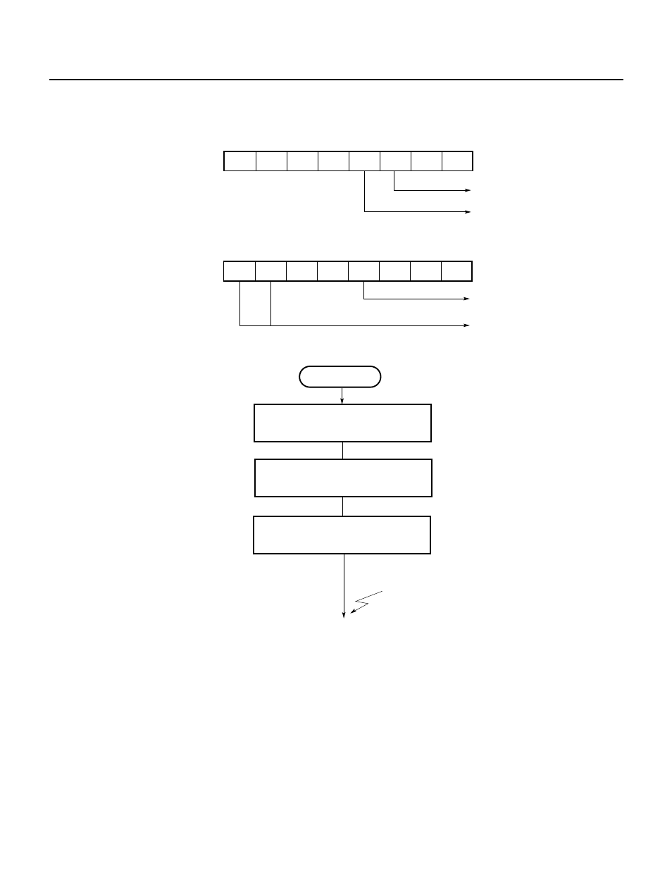
Fig. 7-29 Setting of Control Registers for Interval Timer Operation (2)
(a) Timer control register 0 (TMC0)
7
6
5
4
3
2
1
0
0
0
0
0
1
0
0
1
CRC0
Clears TM0 when CR01 coincides
with TM0
Both TO0 and TO1 are used for
toggle output
(b) Capture/compare control register 0 (CRC0)
Fig. 7-30 Setting Procedure for Interval Timer Operation (2)
Interval timer (2)
Set count value in CR01 register
Set CRC1 register
Start counting
; Sets bit 3 of TMC0 to 1
INTC01 interrupt
CE0
←1
CRC0
←18H
CR01
←n
(3) Pulse width measurement operation
In pulse width measurement, the width of the high level or low level of an external pulse signal applied to the
external interrupt request (INTP3) input pin is measured.
A pulse signal applied to the INTP3 pin must have a pulse width of 12 system clock pulses (2
µs: f
CLK
= 6 MHz)
or more for both the high level and the low level. If the pulse width is less than this value, no valid edge can
be detected, thus resulting in a failure to perform capture operation.
This pulse width measurement allows a pulse width of 2.6
µs to 87.4 ms to be measured with a resolution of
1.3
µs (at f
CLK
= 6 MHz).
As shown in Fig. 7-31, the value of 16-bit timer 0 (TM0) in count operation is loaded and held in the CR02
capture register on a valid edge (either a rising edge or falling edge) of a signal applied to the INTP3 pin. The
pulse width of the input signal is found by multiplying the count clock (8/f
CLK
) by the difference between the
TM0 count value (D
n
) loaded and held in the CR02 register on the n-th valid edge detected and the TM0 count
value (D
n-1
) loaded and held in the CR02 register on the (n – 1)-th valid edge detected.
Fig. 7-32 shows the setting of control registers, and Fig. 7-33 shows the setting procedure.
★
7
6
5
4
3
2
1
0
0
0
0
0
0
0
1
TMC0
Overflow flag
Enables counting TM0
Ч