1 internal program memory area – NEC PD78214 User Manual
Page 71
42
µ
PD78214 Sub-Series
3.1.1 Internal Program Memory Area
In the area from 00000H to 03FFFH (00000H to 01FFFH for the
µPD78212), a 16K × 8 bit ROM (8K × 8 bit ROM for
the
µPD78212) is incorporated. Programs and table data are stored in this area. Usually, the program counter (PC)
is used for addressing.
If the
µPD78213 is used or if the EA pin is driven low, this area becomes external memory (ROM-less operation).
(1) Vector table area
The 64-byte area from 00000H to 0003FH is reserved as a vector table area. Stored in the vector table area
is the program start address to which a program is branched if RESET is input or if an interrupt request occurs.
The low-order eight bits of the 16-bit address are stored at even-numbered addresses, and the high-order
eight bits at odd-numbered addresses.
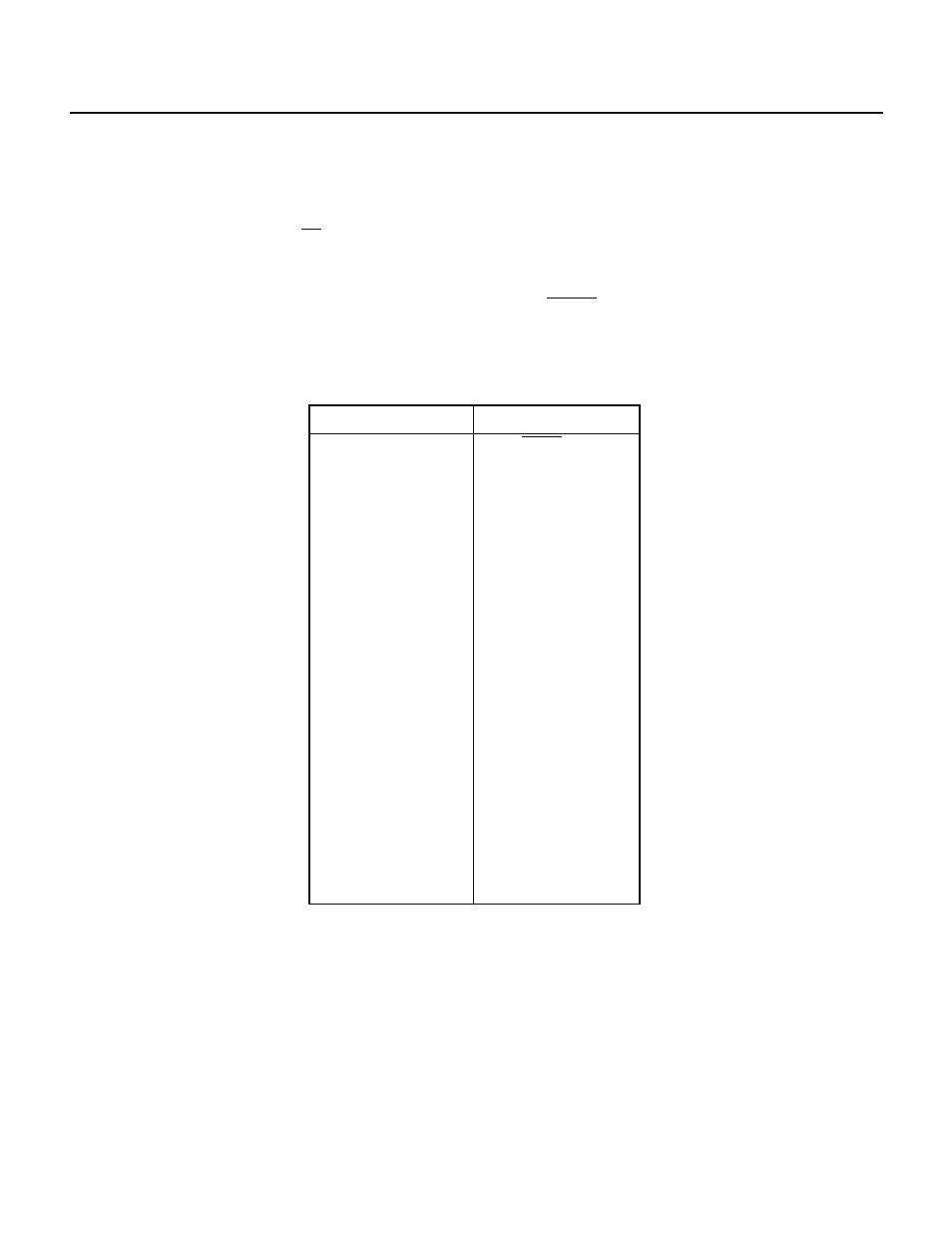
Table 3-1 Vector Table
Vector table address
00000H
00002H
00006H
00008H
0000AH
0000CH
0000EH
00010H
00012H
00014H
00016H
00018H
0001AH
0001CH
00020H
00022H
00024H
00026H
0003EH
Interrupt request
Reset (RESET input)
NMI
INTP0
INTP1
INTP2
INTP3
INTP4/INTC30
INTP5/INTAD
INTC20
INTC00
INTC01
INTC10
INTC11
INTC21
INTSER
INTSR
INTST
INTCSI
BRK
(2) CALLT instruction table area
In the 64-byte area from 00040H to 0007FH, the subroutine entry address of a one-byte call instruction (CALLT)
can be stored.
(3) CALLF instruction entry area
A two-byte call instruction (CALLF) can directly call a subroutine, starting from an address between 00800H
and 00FFFH.