NEC PD78214 User Manual
Page 453
424
µ
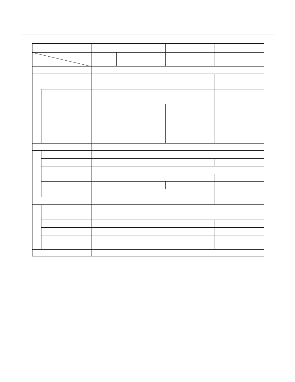
PD78214 Sub-Series
Series name
µPD78214 Sub-Series
µPD78218A Sub-Series
µPD78224 Sub-Series
µPD78214
(
µPD78P214)
PWM output
Comparator
µPD78213
µPD78212
µPD78224
(
µPD78P224)
µPD78220
µPD78218A
(
µPD78P218A)
µPD78217A
Product name
Item
None
8 bits
× 8
Selected according to operating frequency
4 bits
× 8
None
—
None
A/D converter
Pins selected by bits ANI0 to ANI2 of
the ADM register. Pin voltage is
always 0 V to AV
REF
.
Pins subject to A/D
conversion. Pin voltage
is 0 V to AV
REF
during
A/D conversion.
—
3.4 V to V
DD
—
3.6 V to V
DD
None
D/A converter
16-bit timer/counter
8-bit timer/counter
Timer output
PWM/PPG output
One-shot pulse
Interrupt source
External SFR area
UART
CSI
BRG timer
Baud rate generator
External baud rate clock
input
Real-time output port
1
3
2
4
Provided
None
None
None
7
5
16 bytes (0FFD0H to 0FFDFH)
None
1 channel
1 channel (SBI)
Provided (shared with timer/counter 3)
Provided
Provided
Timer/counter
Serial interface
Provided
None
Provided
None
4 bits
× 2 or 8 bits × 1
Selection of conversion time
AV
REF
input voltage
range
Restrictions on input
voltage