3 operation, 4 built-in pull-up resistor, 5 notes – NEC PD78214 User Manual
Page 122: 9 notes
93
Chapter 5 Port Functions
5
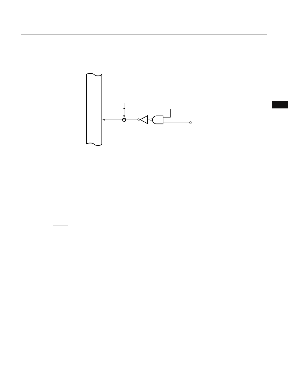
5.8.3 Operation
Port 7 is an input-only port, and the level of its pins can be read and tested.
Fig. 5-44 Port Specified as an Input Port
Internal bus
RD
IN
P7n
n = 0 to 5
5.8.4 Built-In Pull-Up Resistor
Port 0 has no built-in pull-up resistor.
5.8.5 Notes
(1) When P70 through P75 are used as analog input pins AN0 and AN5 respectively or when A/D conversion is
not performed, do not apply a voltage out of the range AV
SS
through AV
REF
to the pins that are selected for
ANI0 through ANI2 of the A/D converter mode register (ADM).
See Chapter 8 for details.
(2) Port 7 is a 6-bit input port. The upper 2 bits of “8-bit” data from port 7 are undefined.
5.9 NOTES
(1) When the RESET signal is input, all the port pins are set to high-impedance (disconnected from their built-in
pull-up resistors).
If it is necessary to prevent a port pin from being set to high-impedance state when the RESET signal is being
supplied, take an appropriate action using an external circuit.
(2) Some operations of the pull-up-resistor-option register (PUO), which is used to specify connection of built-
in pull-up resistors, cannot be emulated by an in-circuit emulator, because of the following restrictions:
• The contents of the PUO register cannot be read correctly.
• Bit manipulation instructions or logical/arithmetic instructions do not work for the PUO register; an SFR
illegal access break may occur, aborting emulation.
• No built-in pull-up resistor is provided.
Therefore, observe the following two points.
• To set the PUO register, use only an 8-bit data transfer instruction (MOV).
• When debugging the target board, use pull-up resistors provided on it.
(3) Supplying the RESET signal does not initialize the contents of the output latch. When using a port in the output
mode, initialize the output latch before turning on the output buffer. Otherwise, data output from the output
ports is unpredictable.
Similarly, to use a port as a control pin, always initialize the internal hardware before specifying the control
pin.