4 interrupt request from the a/d converter, 5 setting for use of an6 and an7, 6 notes – NEC PD78214 User Manual
Page 268: Chapter 8 a/d converter
239
Chapter 8 A/D Converter
8
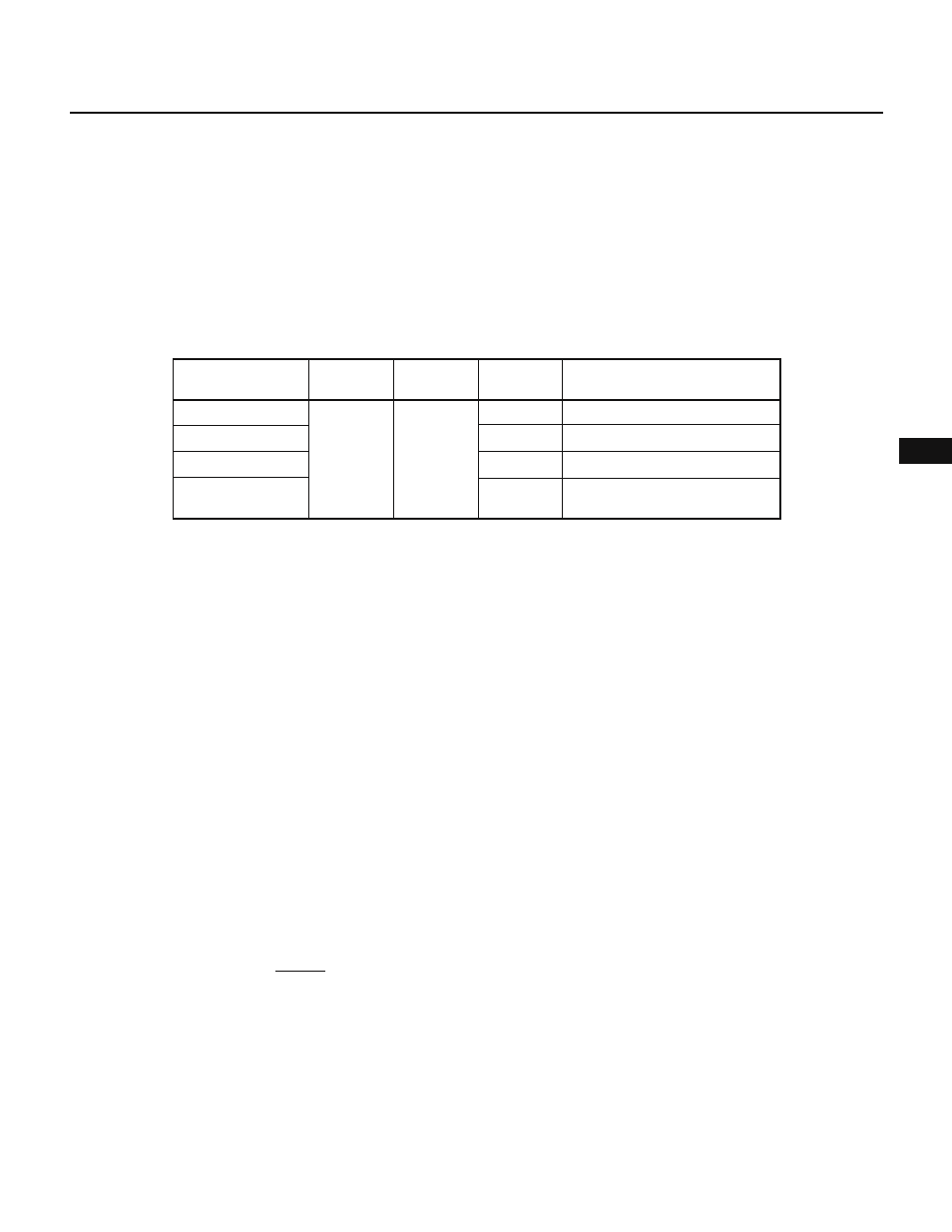
8.4 INTERRUPT REQUEST FROM THE A/D CONVERTER
The A/D converter generates an A/D conversion end interrupt request (INTAD), each time a conversion sequence
is completed, except for the select mode.
The interrupt control flags are shared by the INTAD interrupt and the INTP5 external interrupt. Therefore, the
timing at which an interrupt request occurs varies depending on the mode of A/D conversion specified in the ADM
register, as listed in Table 8-3.
The INTAD interrupt is handled using the interrupt control register in the same manner as the INTP5 interrupt. See
Chapter 12 for details.
Table 8-3 Conditions to Generate Interrupt Requests in Each A/D Converter Operating Mode
Stop
Scan mode
Select mode
Hardware-started
A/D conversion
A/D converter
operation
Interrupt
request flag
INTP5
INTAD
INTP5
INTAD
Interrupt
request
Valid edge input to the INTP5 pin
A/D conversion end
Valid edge input to the INTP5 pin
A/D conversion end
PIF5
PMK5
Mask flag
8.5 SETTING FOR USE OF AN6 AND AN7
When using AN6 or AN7, set up as follows:
(1) When using AN6
• Specify an internal weight (according to the MM and PW registers)
• Specify P66 as an input port (PM66 = 1)
• Do not use an internal pull-up resistor (PUO6 = 0)
(2) When using AN7
• Inhibit refresh (RFEN = 0)
• Specify P67 as an input port (PM67 = 1)
• Do not use an internal pull-up resistor (PUO6 = 0)
8.6 NOTES
(1) Range of voltages applied to analog input pints
When using the A/D converter input pins AN0 through AN7 (P66, P67, P70 through P75, observe the following
points. Otherwise, the
µPD78214 may be damaged.
(a) Do not apply voltages out of the range of AV
SS
to AV
REF
to the pin subjected to A/D conversion.
(b) If the A/D converter is not in use (not operating), do not apply voltages out of the range of AV
SS
through
AV
REF
to the pin
Note
selected by the A/D converter mode register (ADM).
Especially after the RESET signal is input, observe the following points, because AN0 (P70) is selected
automatically.
(i) When you clamp the AV
REF
pin to the V
SS
level, also clamp the AN0 (P70) pin to the V
SS
level.
(ii) When you use the AN0 (P70) pin, clamp the AV
REF
to the V
DD
level or keep the input to the AN0 (P70)
pin below the potential at the AV
REF
pin.
Note
If the MS bit is 1, a pin selected by the ADM register is a pin subjected to A/D conversion. If the MS bit = 0, a pin selected
by the ADM register is the AN0 pin.
Condition to generate interrupt
requests