8 basic operation of output control circuit, Chapter 7 timer/counter units – NEC PD78214 User Manual
Page 208
179
Chapter 7 Timer/Counter Units
7
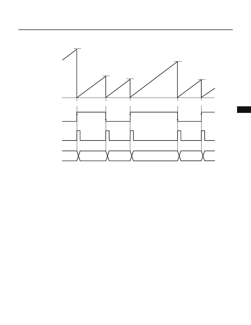
Fig. 7-83 TM2 Cleared after Capture Operation
Remark CLR21 = 0, CLR22 = 1
7.3.8 Basic Operation of Output Control Circuit
The output control circuit controls the levels of the timer outputs (TO2, TO3) according to the coincidence signal
from the compare registers. The operation of the output control circuit is determined by timer output control
register (TOC) and capture/compare control register 2 (CRC2). (See Table 7-15.) Before a timer output (TO0 or TO1)
signal can be output on a pin, the pin must be placed in the control mode by the PMC3 register.
Captured
Captured
Captured
Captured
Captured
Capture/compare
register (CR22)
N4
N5
N3
N2
N1
0H
TM2
count value
INTP1
interrupt request
INTP1
pin output
N1
N2
N3
N4