3 operation, 1 basic a/d converter operation – NEC PD78214 User Manual
Page 259
230
µ
PD78214 Sub-Series
8.3 OPERATION
8.3.1 Basic A/D Converter Operation
(1) A/D conversion sequence
The A/D converter operates as follows:
(a) The input selector selects one of the analog input pins (AN0 through AN7) according to the mode of
operation specified in the A/D converter mode register (ADM).
(b) The sample and hold circuit samples the voltage at the analog input pin selected by the input selector.
(c) After a certain sampling period, the sample and hold circuit goes on hold and retains the input analog
voltage until A/D conversion ends.
(d) When bit 7 of the SAR register is set, the tap selector sets the voltage tap of the serial resistor string to
(255/512)AV
REF
( (1/2)AV
REF
).
(e) The voltage comparator compares the voltage at the serial resistor string with an input analog signal
voltage. If the analog input signal voltage is greater than (1/2)AV
REF
, the MSB of the SAR register remains
set. If it is less than (1/2)AV
REF
, the MSB is reset.
(f) Bit 6 of the SAR register is set to 1 automatically, and the voltage comparator starts comparing the next
analog input signal voltage. A voltage tap of the serial resistor string is selected as follows, according to
the state of bit 7, which has already been set according to the result.
• Bit 7 = 1 (383/512)AV
REF
(3/4)AV
REF
• Bit 7 = 0 (127/512)AV
REF
(1/4)AV
REF
The voltage at this tap is compared with the input analog voltage. According to the comparison result,
bit 6 of the SAR register is set or reset as follows:
• Analog input voltage
≥ voltage tap voltage: Bit 6 = 1
• Analog input voltage
< voltage tap voltage: Bit 6 = 0
(g) These comparisons are carried out successively until the least significant bit (bit 0) of the SAR register is
compared (binary search method).
(h) When all the 8 bits of the SAR register have been compared, a valid digital number is left in the SAR
register. This digital number is sent to and latched in the ADCR register.
At the same time, an A/D conversion end interrupt (INTAD) can be generated (except in software-started
select mode). This INTAD interrupt should be handled as either a vectored interrupt or by a macro service
(described later).
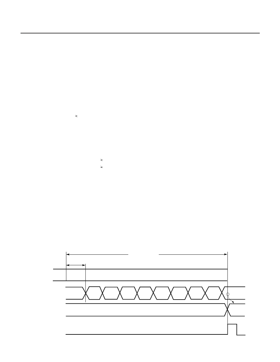
Fig. 8-4 Basic A/D Converter Operation
Note Except for software-started select mode
...
...
Conversion time
Sampling time
A/D converter
operation
SAR
ADCR
A/D conversion
Sampling
Undefined
C0H or
40H
80H
INTAD
Note
Conversion
result
Conversion
result