NEC PD78214 User Manual
Page 213
184
µ
PD78214 Sub-Series
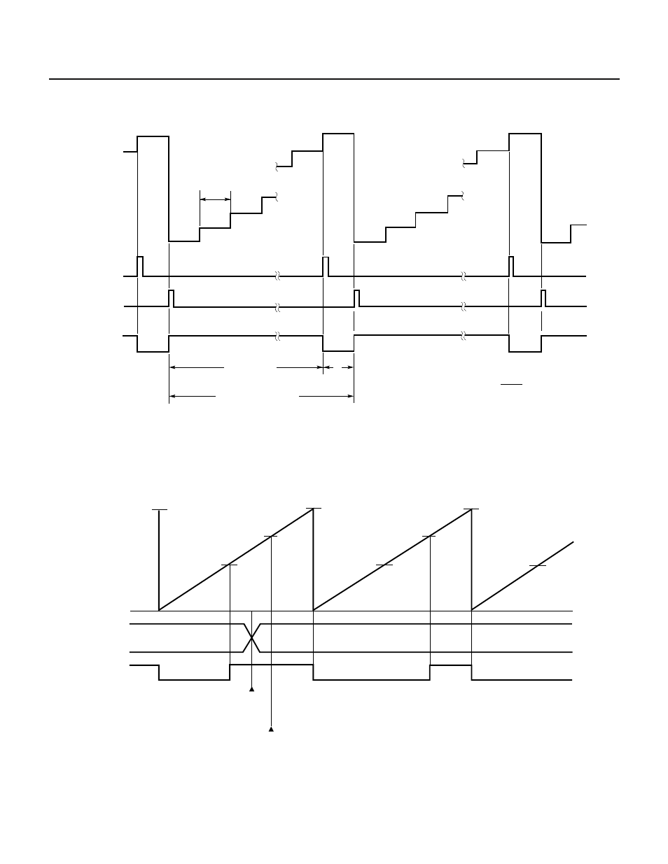
Fig. 7-87 PWM Output When CR20 = FFH
Remark ALV2 = 0
Even if the value of a compare register (CR20, CR21) coincides with the value of 8-bit timer 2 (TM2) more than once
during one period of PWM output, the output levels on the timer outputs (TO2, TO3) are not inverted.
Fig. 7-88 Example of Rewriting a Compare Register
TO2
T1
T2
T1
T1
T1
T2
T2
FFH
TM2
count value
0H
CR20
Rewriting
CR20
TO2 does not change though CR20 coincides with TM2
FFH
FFH
Remark ALV2 = 1
FFH
INTO20
TO2
TM2
count value
Count clock period T
OVF flag
Duty factor =
× 100 = 99.6 (%)
0
1
2
0
1
2
0
Pulse width
Pulse period = 256T
255
256
T
FFH
FFH
FFH
FFH