NEC PD78214 User Manual
Page 235
206
µ
PD78214 Sub-Series
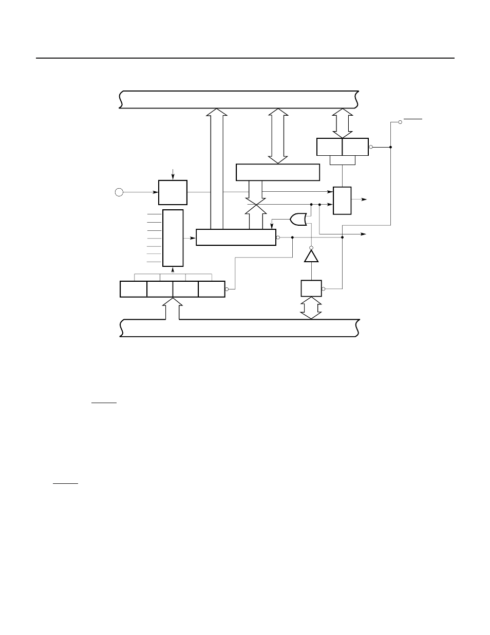
Fig. 7-122 Block Diagram of 8-Bit Timer/Counter 3
INTP4/ASCK
ES41,ES40
8
8
1/8
ES41
ES40
INTP4
INTC30
f
CLK
/512
f
CLK
/256
f
CLK
/128
f
CLK
/64
f
CLK
/32
f
CLK
/16
f
CLK
/8
MPX
PRS3
PRS2
PRS1
PRS0
8
Internal bus
8
Timer control
register 0 (TMC0)
CE3
Prescaler mode
register (PRM0)
Edge
detector
Internal bus
Compare register (CR30)
Coincidence
Clear
Selector
Serial interface
INTP4
RESET
8-bit timer 3 (TM3)
(1) 8-bit timer 3 (TM3)
TM3 is a timer for counting up with the count clock specified by the lower 4 bits of prescaler mode register
0 (PRM0).
TM3 allows only read operation using an 8-bit manipulation instruction. The count operation of TM3 can be
enabled or disabled by timer control register 0 (TMC0).
When the RESET signal is applied, TM3 is cleared to 00H, and count operation stops.
(2) Compare registers (CR30)
The CR30 register is an 8-bit registers for holding a value that determines the period of interval timer
operation.
When the value of the CR30 register coincides with the value of TM3, the value of TM3 is automatically cleared,
and an interrupt request (INTC30) is generated.
The CR30 register allows both read and write operations using an 8-bit manipulation instruction. When the
RESET signal is applied, the CR30 register becomes undefined.
(3) Prescaler
The prescaler generates count clocks from the internal system clock. From these count clocks generated by
the prescaler, a count clock is selected with the selector for the timer to perform count operation.