9 pwm output – NEC PD78214 User Manual
Page 211
182
µ
PD78214 Sub-Series
Table 7-16 TO2 and TO3 Toggle Output (f
CLK
= 6 MHz)
Count clock
f
CLK
/16
f
CLK
/32
f
CLK
/64
f
CLK
/128
f
CLK
/256
f
CLK
/512
Maximum pulse width
2
8
× 16/f
CLK
(683
µs)
2
8
× 32/f
CLK
(1.37 ms)
2
8
× 64/f
CLK
(2.73 ms)
2
8
× 128/f
CLK
(5.46 ms)
2
8
× 256/f
CLK
(10.9 ms)
2
8
× 512/f
CLK
(21.75 ms)
Minimum pulse width
2.6
µs
5.3
µs
10.7
µs
21.3
µs
42.7
µs
85.3
µs
Caution When using an in-circuit emulator, see the notes described in Section 7.5.4.
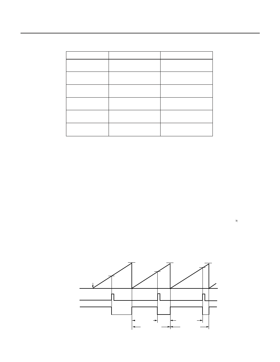
7.3.9 PWM Output
The PWM output function outputs a PWM signal whose period coincides with the full-count period of 8-bit timer
2 (TM2). The pulse width of TO2 is determined by the value of CR20, and the pulse width of TO3 is determined
by the value of CR21. Before this function can be used, the CLR21 and CLR22 bits of capture/compare control
register 2 (CRC2) must be set to 0, and the CMD2 bit of timer control register 1 (TMC1) must be set to 0.
The pulse period and pulse width are as follows:
• PWM period = 256
× x/f
CLK
• PWM pulse width = ((value set in compare register
Note
)
× x + 2)/f
CLK
; x = 16, 32, 64, 128, 256, 512
Note Zero cannot be set in the compare registers.
• Duty factor = (PWM pulse width)/(PWM period) = ((value set in compare register)
× x + 2)/(256 × x) (value set
in compare register)/256
Caution In PWM output, the actual pulse width is longer than a value obtained with the approximate expression by two clock pulses of f
CLK
for the active level, and is shorter than such an approximate value by two clock pulses of f
CLK
for the inactive level. Take this point
into consideration when high-precision output is required or a high-speed count clock is used.
Fig. 7-85 PWM Pulse Output
★
Remark ALV2 = 0
FFH
TO2
0H
Count value of timer
Count starts
CR20
CR20
CR20
Interrupt
Pulse width
Pulse period
Pulse period
Pulse width
FFH
FFH