Chapter 7 timer/counter units – NEC PD78214 User Manual
Page 166
137
Chapter 7 Timer/Counter Units
7
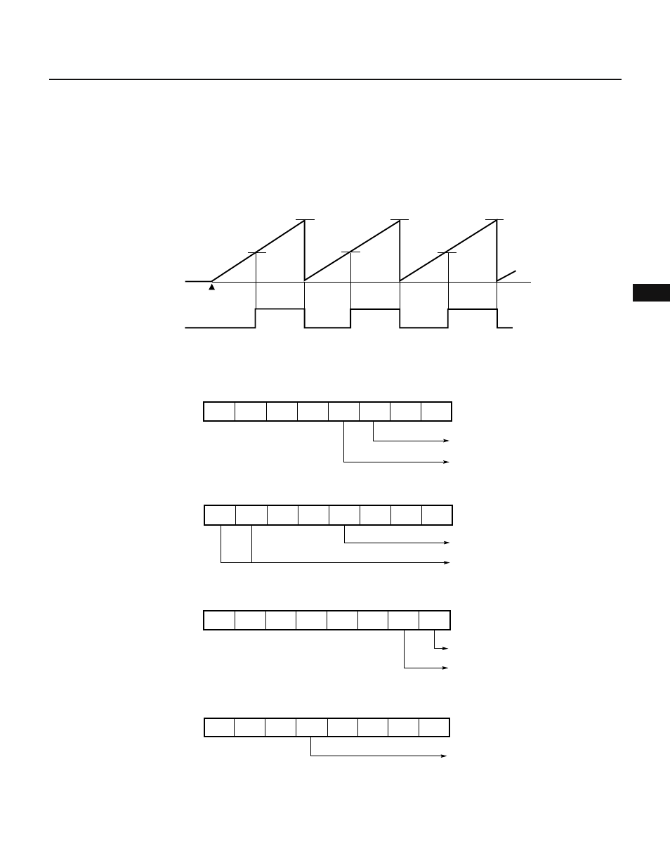
(5) PPG output operation
In PPG output operation, a pulse signal with a period and duty factor determined by the values set in the
compare registers is output. (See Fig. 7-39.)
Fig. 7-40 shows the setting of control registers. Fig. 7-41 shows the setting procedure. Fig. 7-42 shows the
procedure for changing the duty factor of PPG output.
Fig. 7-39 Example of PPG Signal Output by 16-Bit Timer/Counter
CR00
CR00
CR00
Timer starts
0H
TM2
count value
(active low)
TO0
CR01
CR01
CR01
Fig. 7-40 Setting of Control Registers for PPG Output Operation
(a) Timer control register 0 (TMC0)
(b) Capture/compare control register 0 (CRC0)
(c) Timer output control register (TOC)
(d) Port 3 mode control register (PMC3)
★
7
6
5
4
3
2
1
0
1
0
0
0
0
1
CRC0
1
1
Clears when TM0 coincides
with CR01
TO0 is used for PPG output
7
6
5
4
3
2
1
0
TOC
1
1
Ч
Ч
Ч
Ч
Ч
Ч
TO0 for low-active PPG signal output
Enables PPG output for TO0
7
6
5
4
3
2
1
0
Ч
Ч
Ч
Ч
Ч
Ч
Ч
1
PMC3
Specifies P34 pin as TO0
output
7
6
5
4
3
2
1
0
0
0
0
0
0
0
1
TMC0
Overflow flag
Enables counting TM0
Ч