4 operations in the three-wire serial i/o mode, 1 basic operation timing, Chapter 10 clock synchronous serial interface – NEC PD78214 User Manual
Page 294
265
Chapter 10 Clock Synchronous Serial Interface
10
10.4 OPERATIONS IN THE THREE-WIRE SERIAL I/O MODE
In three-wire serial I/O mode, the device can communicate with a device having a conventional clock synchronous
serial interface.
Basically, communication is performed over three lines of serial clock (SCK), serial data output (SO) and serial data
input (SI). A handshaking line is required to connect the device to two or more devices.
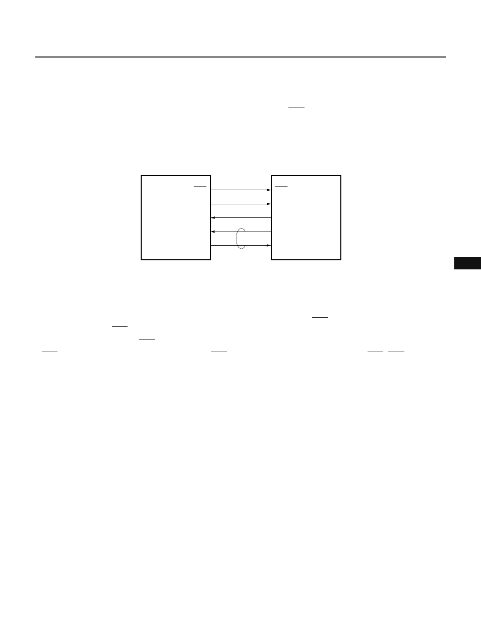
Fig. 10-4 Sample System Configuration with Three-Wire Serial I/O
Three-wire serial I/O
↔ three-wire serial I/O
SCK
SO
SI
Port (interrupt)
Port
SCK
SI
SO
Port
Interrupt (port)
Note
Master CPU
Slave CPU
Note Handshaking line
10.4.1 Basic Operation Timing
In three-wire serial I/O mode, data is transmitted and received in units of eight bits. The data is transmitted and
received one bit at a time by means of the MSB-first method, in synchronization with the serial clock.
The transmission data is output in synchronization with the falling edge of SCK. The reception data is sampled
at the rising edge of SCK.
At the eighth rising edge of SCK, interrupt request INTCSI is issued.
If SCK is used as the internal clock, the output of SCK is stopped at the eighth rising edge of SCK. SCK is tied high
until transmission or reception of the subsequent data is started.
Fig. 10-5 shows the timing chart for three-wire serial I/O mode.