2 prom programming mode, 2 pin functions, 1 normal operating mode – NEC PD78214 User Manual
Page 56: Chapter 2 pin functions, 2 pin functions 2.2.1 normal operating mode
27
Chapter 2 Pin Functions
2
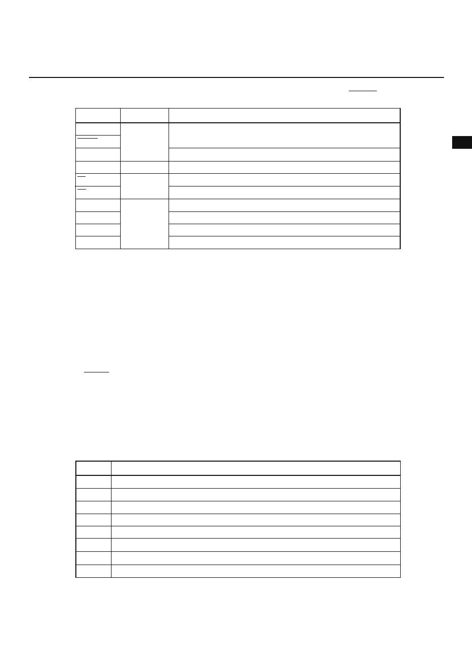
2.1.2 PROM Programming Mode (only for the
µPD78P214, P20/NMI = 12.5 V, RESET = L)
Pin
P20/NMI
RESET
A0-A14
D0-D7
CE
OE
V
PP
V
DD
V
SS
NC
Function
Address bus
Data bus
PROM enable input
Read strobe to PROM
Power for programming
Main power
Ground
—
Input
Input/output
Input
—
Input/output
Setting PROM programming mode
2.2 PIN FUNCTIONS
2.2.1 Normal Operating mode
(1) P00 to P07 (Port 0): Tristate outputs
Port 0, an eight-bit output port with output latches, can directly drive transistors. Its eight bits can be
simultaneously set to either output mode or high impedance mode by specifying the port-0 mode register
(PM0) accordingly.
Port 0 can output the contents of the buffer registers (P0L, P0H) in real-time at any interval, in units of eight
or four bits (P00 to P03 and P04 to P07). The real-time output port control register (RTPC) determines whether
port 0 is used as a normal output port or real-time output port.
When the RESET signal is input, the output of port 0 becomes high impedance, resulting in the contents of
the output latches becoming undefined.
(2) P20 to P27 (port 2): Inputs
Port 2 is an eight-bit input port. P22 to P27 are provided with software-programmable pull-up resistors. P20
to P27 also act as input pins for control signals such as external interrupts (see Table 2-1). To prevent
malfunctions caused by noise, port 2 provides Schmitt-triggered input circuits.
Table 2-1 Port 2 Functions
Note An NMI input is received regardless of whether interrupts are enabled or disabled.
Port
P20
P21
P22
P23
P24
P25
P26
P27
Function
Input port/NMI input
Note
Input port/INTP0 input/CR11 capture trigger input/trigger signal for real-time output port
Input port/INTP1 input/CR22 capture trigger input
Input port/INTP2 input/CI input
Input port/INTP3 input/CR02 capture trigger input
Input port/INTP4 input/ASCK input
Input port/INTP5 input/external trigger signal for A/D converter
Input port/SI input