Chapter 4 clock generator, 1 configuration and function – NEC PD78214 User Manual
Page 84
55
4
CHAPTER 4 CLOCK GENERATOR
4.1 CONFIGURATION AND FUNCTION
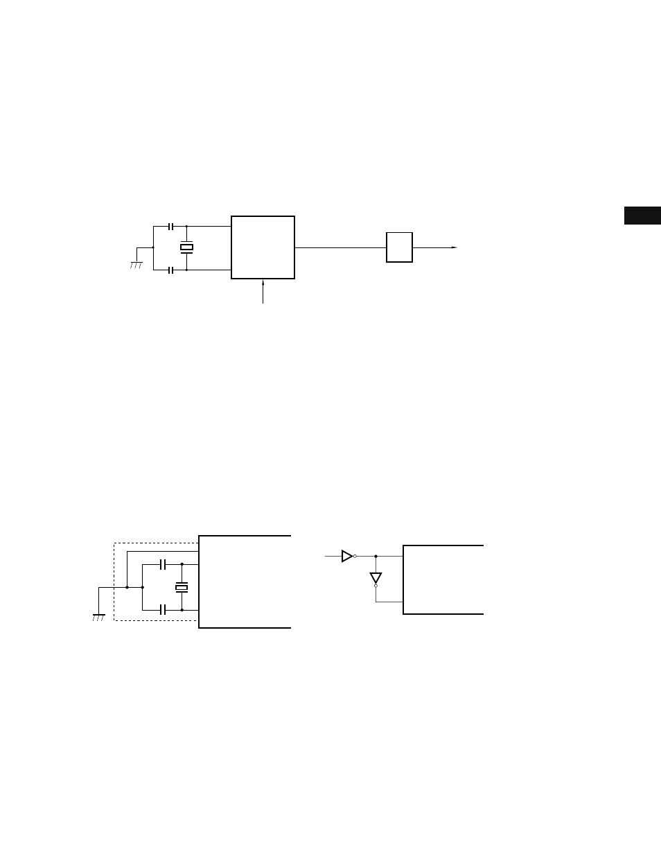
A clock generator generates and controls the internal system clock (CLK) sent to the CPU. Fig. 4-1 shows the
configuration of the clock generator.
Fig. 4-1 Block Diagram of Clock Generator
Remarks f
XX
: Crystal/ceramic oscillation frequency
f
X
: External clock frequency
f
CLK
: Internal system clock frequency (= 1/2·f
XX
or 1/2·f
X
)
The clock oscillator oscillates according to a crystal or ceramic resonator connected to pins X1 and X2. In standby
(STOP) mode, the oscillation is stopped (see Chapter 14).
The external clock can also be input. To input the external clock, input the clock signal to pin X1 and the inverted
signal to pin X2. If the external clock is input, STOP mode cannot be selected.
The frequency divider divides the output from the clock oscillator (f
XX
for the crystal/ceramic oscillation, f
X
for the
external clock) by two and generates the internal system clock (CLK).
Fig. 4-2 External Circuit for the Clock Oscillator
(a) Crystal/ceramic oscillation
(b) External clock
Caution When using the clock oscillator, the adverse influence of stray capacitance must be avoided. When configuring the circuit enclosed
in a dashed line, observe the following:
• Minimize the wiring length.
• Do not let other signal lines cross this circuit.
• Keep this circuit away from lines through which a varying high current flows.
• Always ground the capacitors of the oscillator at the same potential as V
SS
. Do not ground the capacitors to a ground pattern
through which a high current flows.
• Do not draw signals from the oscillator.
★
★
Clock
oscillator
STOP mode
X1
X2
f or f
XX
X
1/2
Frequency
divider
f
CLK
Internal system
clock (CLK)
V
SS
X1
X2
PD78214
µ
PD78214
µ
X1
X2
74HC04, etc.