External device setup manual – IDEC High Performance Series User Manual
Page 81
63
2 Mitsubishi
2
2
2
2
2
2
2
2
2
2
2
2
2
2
2
Con
nection
to a PLC
External Device Setup Manual
2.2.6
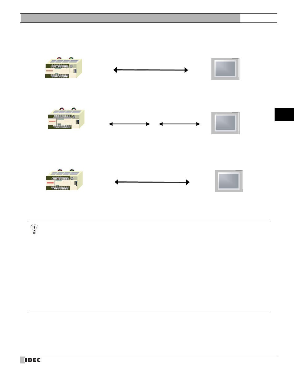
MELSEC-FX Series (connects to the CPU unit programming port)
RS422
MICRO/I
Connection Diagram 4
FX1, FX2, FX2C
MICRO/I
Mitsubishi Cable
RS422
FX20P-CADP
Connection Diagram 4
FX0, FX0N, FX2N, FX2NC
FX3UC, FX3U, FX3G
RS422
MICRO/I
Connection Diagram 10
FX0, FX0N, FX2N, FX2NC
FX3UC, FX3U, FX3G
- In case of HG2F/3F/4F a connection cable is available for Connection Diagram 4 (part number: HG9Z-3C165).
- In case of HG1F a connection cable is available for Connection Diagram 4 (part number: HG9Z-XC255).
- In case of HG2G-5F, HG3G/4G a connection cable is available for Connection Diagram for Connection Diagram 10
(part number: HG9Z-XC305).
- In case of HG2G-S/-5S/-5F, HG3G/4G a connection cable is available for Connection Diagram for Connection Diagram
10
(part number: HG9Z-XC275).
Please do not use the HG9Z-XC275 for the MELSEC-FX3U/FX3UC-32-MT-LT because the Mini Din connector inter-
feres with the housing of the PLC.
- In case of HG1F a connection cable is available for Connection Diagram 10 (part number: HG9Z-XC245).
Please do not use the HG9Z-XC245 for the MELSEC-FX3U/FX3UC-32-MT-LT because the Mini Din connector inter-
feres with the housing of the PLC.