External device setup manual – IDEC High Performance Series User Manual
Page 419
401
14 Koyo
2
2
2
2
2
2
2
2
2
2
2
2
2
2
2
Con
nection
to a PLC
External Device Setup Manual
14.5.3
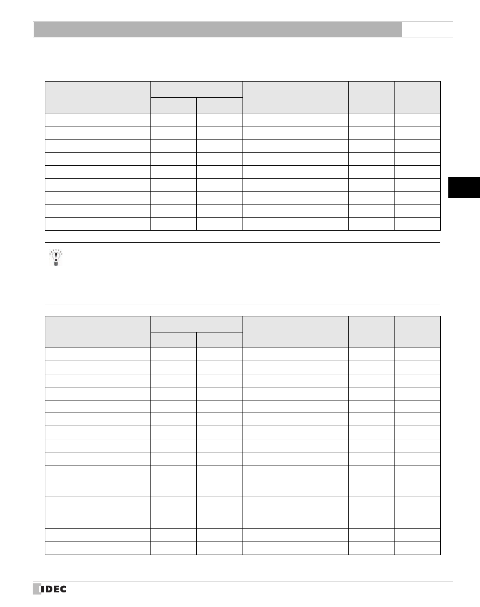
DirectLogic (Ethernet)
Bit Device
Device Name
Device Symbol
Address Range
Read
/Write
Address
Gradual
MICRO/I
PLC
Input Points (Bit)
X
X
0 - 1777
R
8
Output Points (Bit)
Y
Y
0 - 1777
R/W
8
Control Relays (Bit)
C
C
0 - 3777
R/W
8
Special Relays (Bit)
SP
SP
0 - 777
R
8
Timers (Bit)
T
T
0 - 377
R
8
Counters (Bit)
CT
CT
0 - 377
R
8
Stages (Bit)
S
S
0 - 1777
R/W
8
Remote Input (Bit)
GX
GX
0 - 3777
R/W
8
Remote Output (Bit)
GY
GY
0 - 3777
R/W
8
Important points to note regarding setting performing Bit Write operations
With a Bit Write operation, the word data is first read from the PLC, and a logic operation (AND or OR) is performed on
the relevant bit before writing it to the PLC to ensure that the values of other bits in the same channel are preserved.
However, be certain that the PLC does not modify the data in the channel during the time that the MICRO/I is writing the
data.
Word Device
Device Name
Device Symbol
Address Range
Read
/Write
Address
Gradual
MICRO/I
PLC
Input Points (Word)
VX
V
40400 - 40477
R
8
Output Points (Word)
VY
V
40500 - 40577
R/W
8
Control Relays (Word)
VC
V
40600 - 40777
R/W
8
Special Relays (Word)
VSP
V
41200 - 41237
R
8
Timers (Word)
VT
V
41100 - 41117
R
8
Counters (Word)
VCT
V
41140 - 41157
R
8
Stages (Word)
VS
V
41000 - 41077
R/W
8
Timer Current Values
TA
V
0 - 377
R/W
8
Counter Current Values
CTA
V
1000 - 1377
R/W
8
Data Words
V
V
400 - 777
1200 - 7577
10000 - 35777
R/W
8
System parameters
VSYS
V
700 - 777
7400 - 7777
36000 - 37777
R
8
Remote Input (Word)
VGI
V
40000 - 40177
R/W
8
Remote Output (Word)
VGY
V
40200 - 40377
R/W
8