M 2(refer to p610), Diagram 2 (refer to p610), External device setup manual – IDEC High Performance Series User Manual
Page 628
Chapter 5
610
External Device Setup Manual
1.3.2
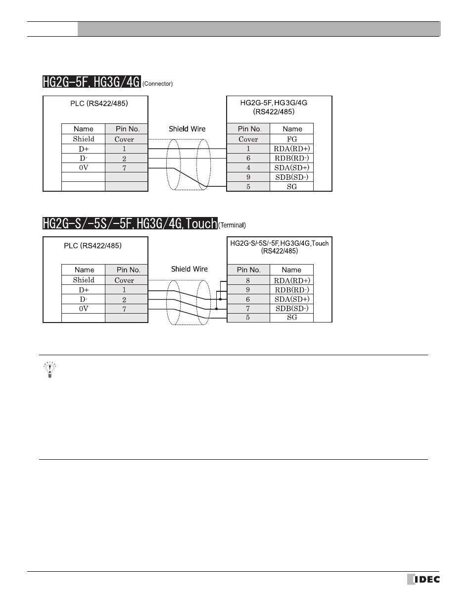
Connection Diagram 2: TWDNAC485D to MICRO/I or Touch
Mini Din 8P
D-sub, 9P connector plug type
Mini Din 8P
Terminal
- There is no pin number corresponding to TERM on the HG2G-S/-5S/-5F, HG3G/4G. When inserting a termination resis-
tor, use a communication switch. For the setting of the switch, refer to Chapter 1 "3 Important Points Regarding Wiring"
on page 19
- HG2G-5F, HG3G/4G Series uses only RDA and RDB when using RS422/485 2-wire, you don’t need to connect SDA or
SDB.
If connecting COM1 on the HG2G-5F, HG3G/4G to the external device, do not insert terminating resistor to the external
device. If terminating resistor can not be removed, use COM2 on the HG2G-5F, HG3G/4G instead of COM1.
- Touch has no pin number corresponding to TERM. When a termination resistor is necessary, insert one with suitable resis-
tance value between pin 8 (RDA) and pin 9 (RDB).