2 o/i link communication settings, O/i link communication settings, 2o/i link communication settings – IDEC High Performance Series User Manual
Page 569: External device setup manual
551
2 O/I Link Communication Settings
3
3
3
3
3
3
3
3
3
3
3
3
3
3
3
O/I Lin
k
Co
mmun
ication
External Device Setup Manual
2
O/I Link Communication Settings
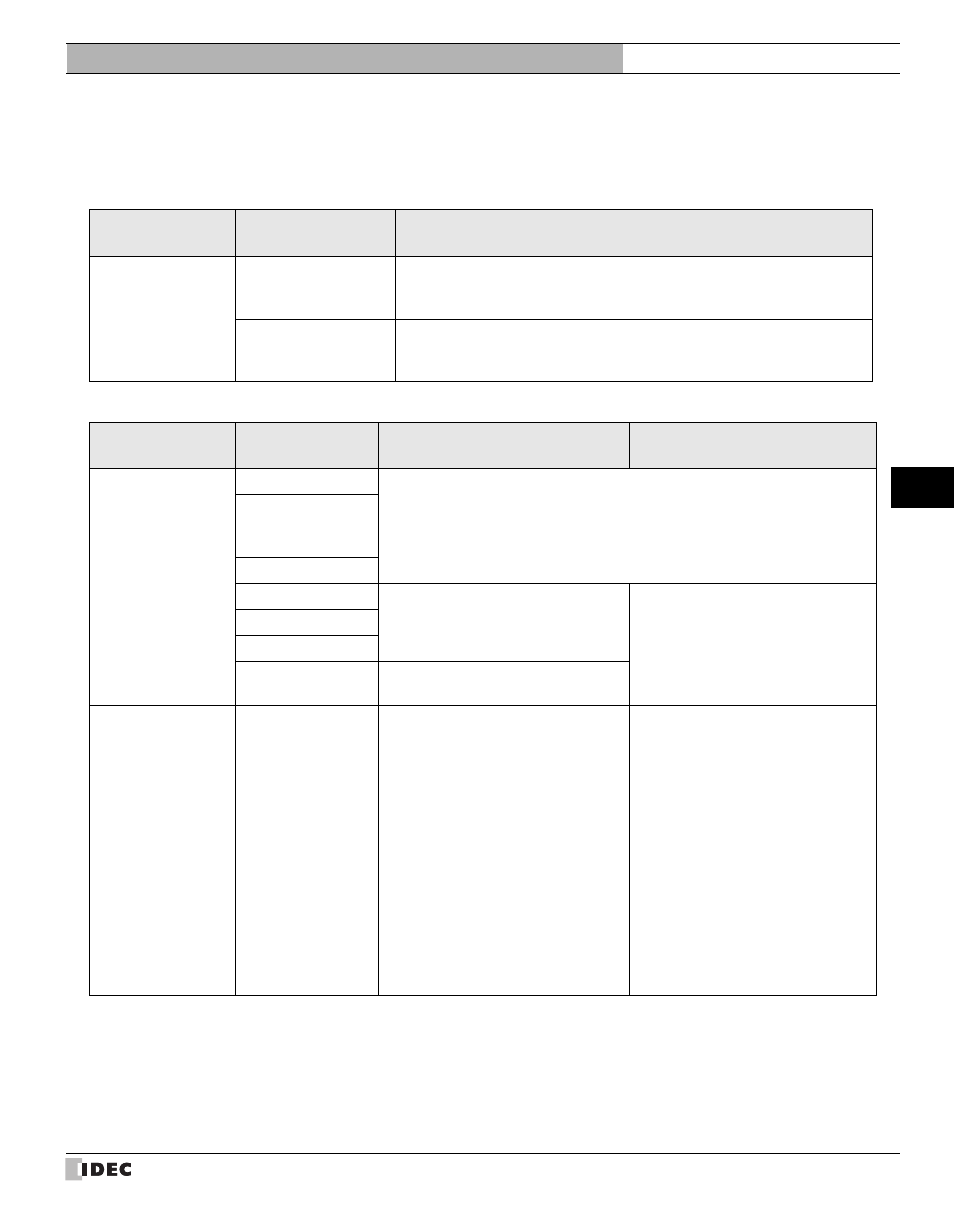
To use the O/I Link Communication, you must set the necessary items in the O/I Link tab of the Configuration - System Setup -
Project dialog box. (Refer to the WindO/I-NV2 User’s Manual or SmartAXIS Touch User's Manual.)
In addition, make the following settings for the PLC Link Communication.
Dialog Box Name
- Tab Name
Setting
Description
Project Settings -
O/I Link
O/I Link Station
Set the MICRO/I or Touch connected to the PLC as the master, and the other
MICRO/I or Touch as slaves (1 to 15). Make sure that the settings do not over-
lap.
Slave Station
MICRO/I or Touch that are connected to the master MICRO/I or Touch (i.e.
the one whose O/I Link Type is registered as Master) must be registered as
slaves (1 to 15). Select the checkbox.
Dialog Box Name
- Tab Name
Setting
Master
Slave 1 to 15
Project Settings -
Host I/F Driver or
Communication
Driver
Manufacturer
Use the same setting for all MICRO/I or Touch.
Host I/F Driver,
Communication
Driver
Connection Type
Transmission Wait
Set it according to the environment.
Setting not required.
Time Out
Retry Cycles
Other
Match to the setting of the PLC that you
will use.
Project Settings -
Communication
Interface
SERIAL 1/COM1
The use of Serial 1 depends on the fol-
lowing selected O/I type :.
HG2G-5F, HG3G/4G series:
Select “O/I Link Slave” as the interface
used for O/I Link communication.
Serial 1 maybe selected as the “O/I
Link Master” for O/I Link communi-
cation, or select “Host Communica-
tion” as the communication interface
for PLC communication.
HG2G-S/-5S, HG1F/2F/3F/4F series:
Select “Host Communication”.
Touch:
Select the External Device Com-
munication.