External device setup manual – IDEC High Performance Series User Manual
Page 213
195
4 Allen-Bradley
2
2
2
2
2
2
2
2
2
2
2
2
2
2
2
Con
nection
to a PLC
External Device Setup Manual
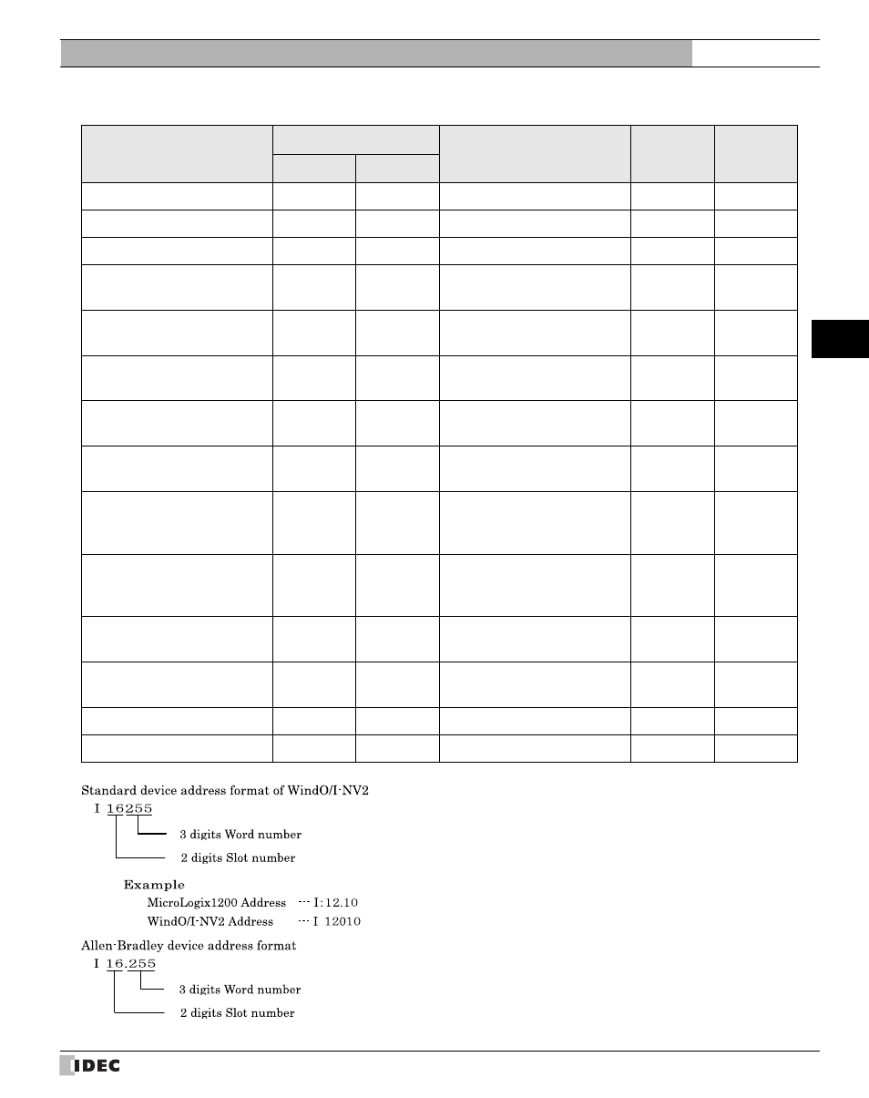
Word Device
Device Name
Device Symbol
Address Range
Read
/Write
Address
Gradual
MICRO/I
PLC
Output
WO
O
0 - 16255
R
10
*1
*1. Address selection rule is as follows.
Input
WI
I
0 - 16255
R
Status
S
S
2000 - 2065
R
10
*2
Bit
WB
B
3000 - 3255,
9000 - 255255
R/W
Timer (Preset Value)
TP
T(P)
4000 - 4255,
9000 - 255255
R/W
Timer (Accumulated Value)
TA
T(A)
4000 - 4255,
9000 - 255255
R/W
Counter (Preset Value)
CP
C(P)
5000 - 5255,
9000 - 255255
R/W
Counter (Accumulated Value)
CA
C(A)
5000 - 5255,
9000 - 255255
R/W
Control
(Number of characters specified
to be sent or received)
RLEN
R(LEN)
6000 - 6255,
9000 - 255255
R/W
Control
(Number of characters actually
sent or received)
RPOS
R(POS)
6000 - 6255,
9000 - 255255
R/W
Integer
N
N
7000 - 7255,
9000 - 255255
R/W
Float Point
F
F
80000 - 82551,
90000 - 2552551
R/W
10
*3
Long Word
L
L
90000 - 2552551
R/W
ASCII
A
A
9000 - 255255
R/W