External device setup manual – IDEC High Performance Series User Manual
Page 226
Chapter 2
208
External Device Setup Manual
WO, WI, WB is same devices as O, I, B. They are used as word devices.
•
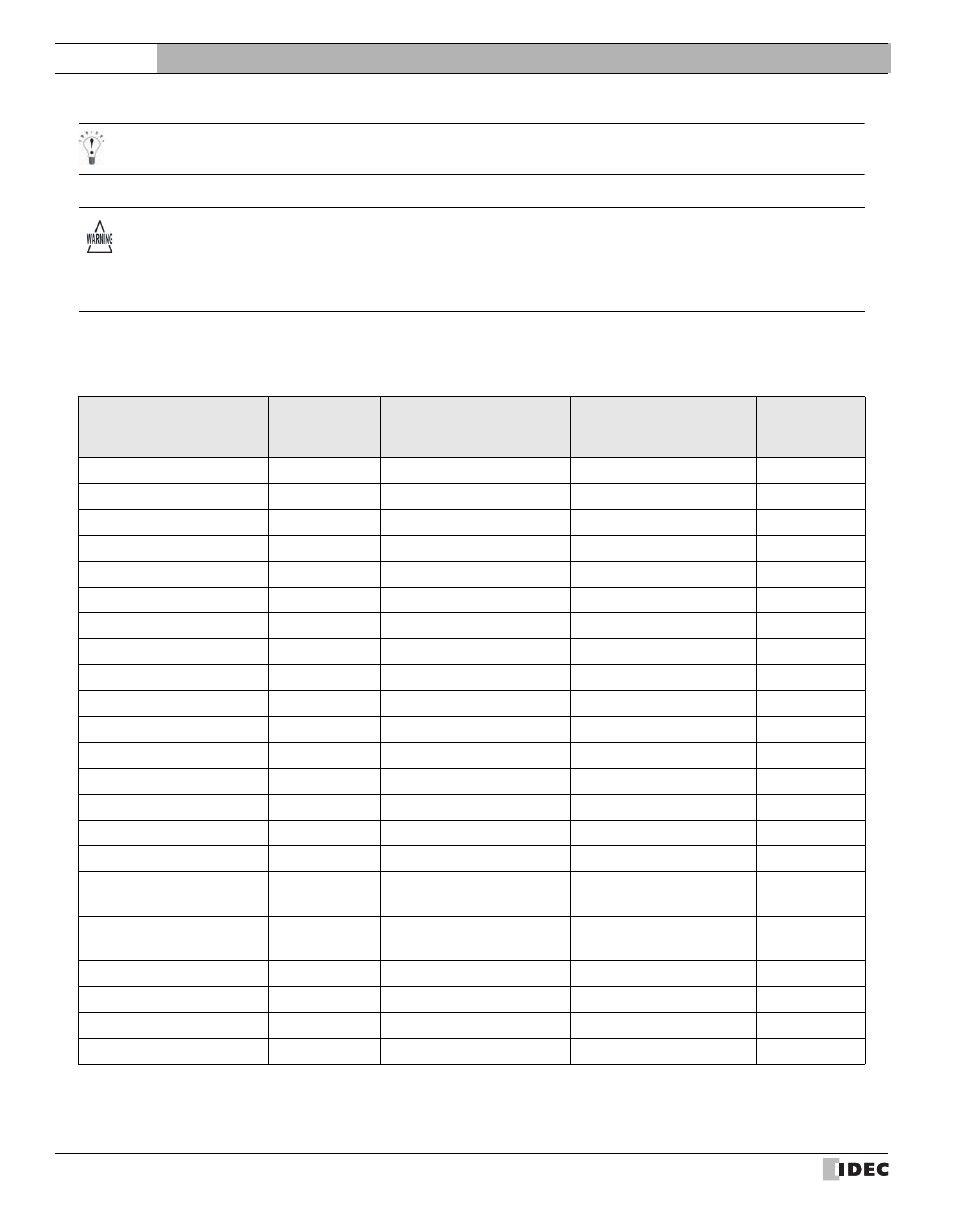
Cross reference table of devices name
- Floating Point (F) and Long Word (L) are 32-bit devices. When you write to these devices, please be sure to write a high
word and low word simultaneously. If you write only high word or only low word, 0 will be written into the other word.
- A communication error will occur if you specify a file or element that is not allocated to the MicroLogis1200, SLC 500
data table map.
Bit Device
Device Name
Device
Symbol
MicroLogix/SLC500
PLC-5
ControlLogix
CompcatLog
ix
SLC/MicroLogix Input
SI
Input (Bit)
-
-
SLC/MicroLogix Output
SO
Output (Bit)
-
-
PLC-5 Input
PI
-
Input (Bit)
-
PLC-5 Output
PO
-
Output (Bit)
-
Binary
B
Binary
Binary
-
Timer Enable bit
TEN
Timer Enable bit
Timer Enable bit
-
Timer Timing Bit
TTT
Timer Timing Bit
Timer Timing Bit
-
Timer Done Bit
TDN
Timer Done Bit
Timer Done Bit
-
Counter Up Enable Bit
CCU
Counter Up Enable Bit
Counter Up Enable Bit
-
Counter Down Enable Bit
CCD
Counter Down Enable Bit
Counter Down Enable Bit
-
Counter Done Bit
CDN
Counter Done Bit
Counter Done Bit
Counter Overflow Bit
COV
Counter Overflow Bit
Counter Overflow Bit
-
Counter Underflow Bit
CUN
Counter Underflow Bit
Counter Underflow Bit
-
Counter Update Accumulator
CUA
Counter Update Accumulator
-
-
Control Enable Bit
REN
Control Enable Bit
-
-
Control Queue Bit
REU
Control Queue Bit
-
-
Control Aynchronous Done
Bit
RDN
Control Aynchronous Done
Bit
-
-
Control Synchronous Done
BIt
REM
Control Synchronous Done
BIt
-
-
Control Error Bit
RER
Control Error Bit
-
-
Control Unload Bit
RUL
Control Unload Bit
-
-
Control Running Bit
RIN
Control Running Bit
-
-
Control Found Bit
RFD
Control Found Bit
-
-