3 connection diagram, Connection diagram, Refer to p127) – IDEC High Performance Series User Manual
Page 145
127
3 Omron
2
2
2
2
2
2
2
2
2
2
2
2
2
2
2
Con
nection
to a PLC
External Device Setup Manual
3.3
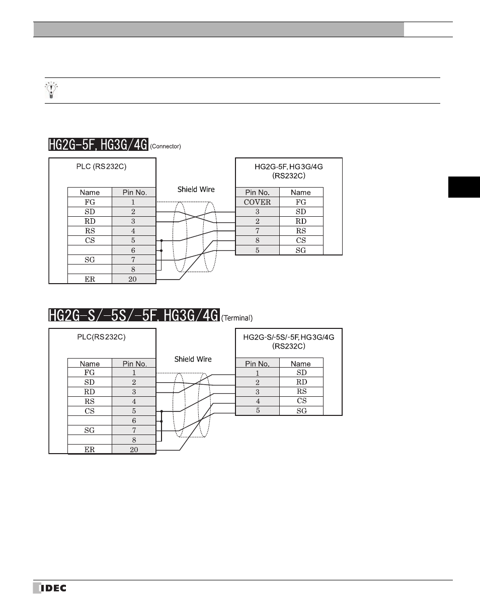
Connection Diagram
For details regarding wiring refer to Chapter 1 "3 Important Points Regarding Wiring" on page 19.
3.3.1
Connection Diagram 1: RS232C Link Unit to MICRO/I
D-sub, 25P connector socket type
D-sub, 9P connector plug type
D-sub, 25P connector socket type
Terminal
This manual is related to the following products: